
Liquid-cooled PM340 Power Module in blocksize format 6SL3215-1SE... |
|
|---|---|
Line connection voltage (up to 2000 m (6562 ft) above sea level) | 380 ... 480 V 3 AC ±10 % (in operation -15 % < 1 min) |
Line system configuration | Grounded TN/TT systems and non-grounded IT systems |
Line frequency | 47 … 63 Hz |
Line power factor with a 3 AC line connection voltage and rated power |
|
| > 0,96 |
| 0.65 … 0.95 |
Overvoltage category to EN 60664-1 | Class III |
Precharging frequency of the DC link | 1 × every 30 s |
DC link voltage, approx. | 1.35 x line voltage |
Output frequency |
|
| 0 … 650 Hz 1) |
| 0 … 300 Hz 1) |
| 0 … 600 Hz 1) |
Electronics power supply | 24 V DC -15 %/+20 % |
Radio interference suppression |
|
| No radio interference suppression |
Type of cooling | Liquid cooling with integrated heat exchanger in stainless-steel version |
Coolant 2)
| 6.0 … 9.0 < 200 mg/l < 240 mg/l < 2.5 mmol/l 3) < 2000 μS/cm < 1000 col/ml 4) < 100 μm |
Cooling circuit 2) |
|
| 600 kPa 70 kPa 80 … 200 kPa Dependent on the ambient temperature, condensation is not permitted |
Permissible ambient temperature (air) during operation | Dependent on the inlet temperature of the coolant, condensation is not permissible |
Installation altitude | Up to 2000 m (3281 ft) above sea level without derating, |
Conformity | CE (Low-Voltage and EMC Directives) |
Approvals, according to | cULus |
Safety Integrated | Safety Integrity Level 2 (SIL 2) acc. to IEC 61508, Performance Level d (PLd) acc. to ISO 13849‑1 and Control Category 3 acc. to ISO 13849‑1 or EN 954‑1. For further information see chapter "Safety Integrated" |
1) Note the correlation between max. output frequency, pulse frequency and current derating.
For further information see chapter "System description – Dimensioning".
2) The values are applicable to coolant (water) without the addition of anti-freeze or inhibitors. When anti-freeze or inhibitors are added, the specifications of the manufacturer regarding water quality must be observed. The proportion of anti-freeze must not exceed a minimum concentration, otherwise the coolant has a marked corrosive effect. In the case of Antifrogen N, the recommended range of the ratio of Antifrogen N to water lies between 20/80 and 45/55 Vol.%
3) The hardness of the coolant, especially the concentration of calcium compounds should be kept to a minimum to prevent the build-up of damaging calcium deposits (lime scale). A hardness < 1.5 mmol/l is recommended.
4) The number of microbes should generally be as low as possible to prevent damage as a result of slime-producing, iron-depositing, corroding bacteria. In closed coolant circuits, the accumulation of microbes can be prevented, for example, by adding anti-freeze. The concentration of anti-freeze must only reach a minimum level to prevent corrosion, see Footnote 2).
Line voltage 380 … 480 V 3 AC | Liquid-cooled Power Module in blocksize format | |||
|---|---|---|---|---|
|
| 6SL3215-1SE23‑8UA0 | 6SL3215-1SE26‑0UA0 | 6SL3215-1SE27‑5UA0 |
Output current |
|
|
|
|
| A | 38 | 60 | 75 |
| A | 33 | 48 | 65 |
| A | 49 | 78 | 98 |
| A | 64 | 90 | 124 |
Type rating 1) |
|
|
|
|
| kW (HP) | 18.5 (25) | 30 (40) | 37 (50) |
| kW (HP) | 15 (20) | 22 (30) | 30 (50) |
Rated pulse frequency | kHz | 4 | 4 | 4 |
Power loss |
|
|
|
|
| kW | 0.38 | 0.69 | 0.99 |
| kW | 0.09 | 0.13 | 0.16 |
Cooling circuit |
|
|
|
|
| dm3/min | 8 | 8 | 8 |
|
| Pipe thread ISO 228 – G ½ B (external thread ½’’, flat-sealing) | Pipe thread ISO 228 – G ½ B (external thread ½’’, flat-sealing) | Pipe thread ISO 228 – G ½ B (external thread ½’’, flat-sealing) |
| dm3 | 0.1 | 0.1 | 0.13 |
Sound pressure level LpA (1 m) at 50/60 Hz | dB | < 60 | < 60 | < 60 |
Rated input current with/without line reactor | A | 40/46 | 63/72 | 78/88 |
Resistance value of the external braking resistor | Ω | ≥ 27 | ≥ 27 | ≥ 15 |
Cable length, max. to braking resistor | m (ft) | 15 (49) | 15 (49) | 15 (49) |
24 V DC power supply for the Control Unit | A | 1.0 | 1.0 | 1.0 |
Line connection U1/L1, V1/L2, W1/L3 |
| Stud M6, | Stud M6, | Stud M6, |
DC link connection, connection for the braking resistor DCP/R1, DCN, R2 |
| Stud M6, | Stud M6, | Stud M6, |
Motor connection U2, V2, W2 |
| Stud M6, | Stud M6, | Stud M6, |
PE connection |
| On housing with M6 screw | On housing with M6 screw | On housing with M6 screw |
Motor cable length, max. |
|
|
|
|
| m (ft) | 70 (230) | 70 (230) | 70 (230) |
| m (ft) | 100 (328) | 100 (328) | 100 (328) |
Degree of protection |
| IP20 | IP20 | IP20 |
Dimensions |
|
|
|
|
| mm (in) | 275 (10.83) | 275 (10.83) | 275 (10.83) |
| mm (in) | 471 (18.54) | 471 (18.54) | 577 (22.72) |
|
|
|
|
|
| mm (in) | 159.5 (6.28) | 159.5 (6.28) | 159.5 (6.28) |
| mm (in) | 240.4 (9.46) | 240.4 (9.46) | 240.4 (9.46) |
| mm (in) | 181.3 (7.14) | 181.3 (7.14) | 181.3 (7.14) |
Frame size |
| FSD | FSD | FSE |
Weight, approx. | kg (lb) | 10.5 (23) | 10.5 (23) | 15 (33) |
1) Rated output of a typical standard asynchronous motor at 400 V 3 AC. For specific sizing select drive based on motor nameplate current and overload.
Line voltage 380 … 480 V 3 AC | Liquid-cooled Power Module in blocksize format | |||
|---|---|---|---|---|
|
| 6SL3215-1SE31‑0UA0 | 6SL3215-1SE31‑1UA0 | 6SL3215-1SE31‑8UA0 |
Output current |
|
|
|
|
| A | 90 | 110 | 178 |
| A | 80 | 95 | 155 |
| A | 117 | 143 | 231 |
| A | 150 | 180 | 290 |
Type rating 1) |
|
|
|
|
| kW (HP) | 45 (60) | 55 (75) | 90 (125) |
| kW (HP) | 37 (60) | 45 (60) | 75 (100) |
Rated pulse frequency | kHz | 4 | 4 | 4 |
Power loss |
|
|
|
|
| kW | 1.21 | 1.42 | 2.31 |
| kW | 0.19 | 0.21 | 0.35 |
Cooling circuit |
|
|
|
|
| dm3/min | 8 | 8 | 8 |
|
| Pipe thread ISO 228 – G ½ B (external thread ½’’, flat-sealing) | Pipe thread ISO 228 – G ½ B (external thread ½’’, flat-sealing) | Pipe thread ISO 228 – G ½ B (external thread ½’’, flat-sealing) |
| dm3 | 0.13 | 0.2 | 0.2 |
Sound pressure level LpA (1 m (3.28 ft)) at 50/60 Hz | dB | < 62 | 62 | 65 |
Rated input current with/without line reactor | A | 94/105 | 115/129 | 186/204 |
Resistance value of the external braking resistor | Ω | ≥ 15 | ≥ 8.2 | ≥ 8.2 |
Cable length, max. to braking resistor | m (ft) | 15 (49) | 15 (49) | 15 (49) |
24 V DC power supply for the Control Unit | A | 1.0 | 1.0 | 1.0 |
Line connection U1/L1, V1/L2, W1/L3 |
| M6 screw stud, | M8 screw stud, | M8 screw stud, |
DC link connection, connection for the braking resistor DCP/R1, DCN, R2 |
| M6 screw stud, | M8 screw stud, | M8 screw stud, |
Motor connection U2, V2, W2 |
| M6 screw stud, | M8 screw stud, | M8 screw stud, |
PE connection |
| On housing with M6 screw | On housing with M8 screw | On housing with M8 screw |
Motor cable length, max. |
|
|
|
|
| m (ft) | 70 (230) | 70 (230) | 70 (230) |
| m (ft) | 100 (328) | 100 (328) | 100 (328) |
Degree of protection |
| IP20 | IP20 | IP20 |
Dimensions |
|
|
|
|
| mm (in) | 275 (10.83) | 350 (13.78) | 350 (13.78) |
| mm (in) | 577 (22.72) | 660 (25.98) | 660 (25.98) |
|
|
|
|
|
| mm (in) | 159.5 (6.28) | 241.5 (9.51) | 241.5 (9.51) |
| mm (in) | 240.4 (9.46) | 322.5 (12.70) | 322.5 (12.70) |
| mm (in) | 181.3 (7.14) | 263 (10.35) | 263 (10.35) |
Frame size |
| FSE | FSF | FSF |
Weight, approx. | kg (lb) | 15 (30) | 29 (64) | 29 (64) |
1) Rated output of a typical standard asynchronous motor at 400 V 3 AC.For specific sizing select drive based on motor nameplate current and overload.
Liquid-cooled Power Modules in blocksize format: Frame sizes FSD, FSE and FSF
Liquid-cooled PM340 Power Modules transfer most of their heat losses to the cooling liquid through the integrated stainless steel heat exchanger. As a result, they can be installed in control cabinets with high degrees of protection. They do not utilize high-maintenance filter mats or ventilation grilles. The units are designed for vertical mounting.
Liquid-cooled PM340 Power Modules have the following interfaces as standard:
Liquid-cooled PM340 Power Modules are available only without integrated line filter and can be connected to grounded TN/TT systems and non-grounded IT systems. The integrated Braking Unit (Braking Chopper) is rated with the capability to permanently energize the braking resistor. The temperature of the external braking resistor must be monitored (i.e. thermostatic switch) to provide protection against thermal overloading.
The scope of supply of the Power Modules includes:
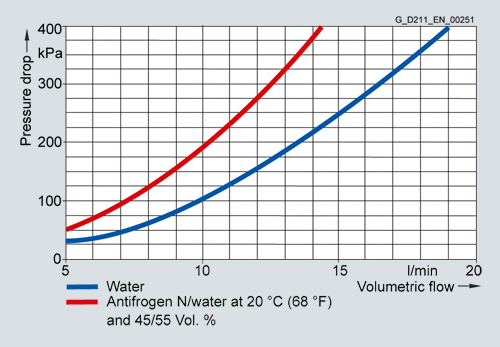
Pressure loss on frame sizes FSD, FSE, FSF
Load cycle data for liquid-cooled PM340 Power Modules in blocksize format

Load cycle with previous load

Load cycle without previous load

S6 load cycle with previous load with a load cycle period of 600 s

S6 load cycle with previous load with a load cycle period of 60 s

Load cycle with 60 s overload with a load cycle period of 300 s

Load cycle with 30 s overload with a load cycle period of 300 s
Output current dependent on pulse frequency
PM340 Power Module in blocksize format | Rated output current | Derating factor |
|---|---|---|
Type | A | for a pulse frequency of 8 kHz |
6SL3215-1SE23-8UA0 | 38 | 0.7 |
6SL3215-1SE26-0UA0 | 60 | 0.7 |
6SL3215-1SE27-5UA0 | 75 | 0.7 |
6SL3215-1SE31-0UA0 | 90 | 0.7 |
6SL3215-1SE31-1UA0 | 110 | 0.7 |
6SL3215-1SE31-8UA0 | 178 | 0.7 |
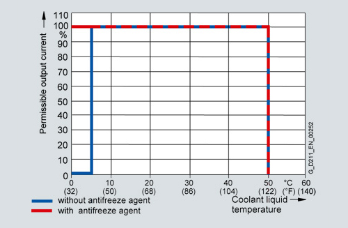
Current derating dependent on temperature of the cooling liquid

Voltage derating dependent on installation altitude
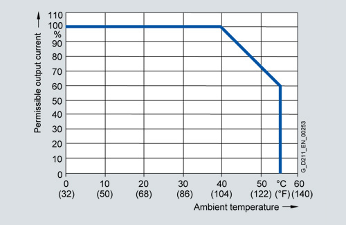
Current derating dependent on ambient temperature
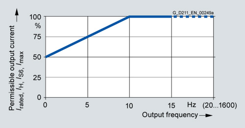
Output current dependent on output frequency
The liquid-cooled PM340 Power Modules in blocksize format communicate with the CU310/SIMOTION D Control Unit or the CUA31/CUA32 Control Unit Adapter via the PM-IF interface.
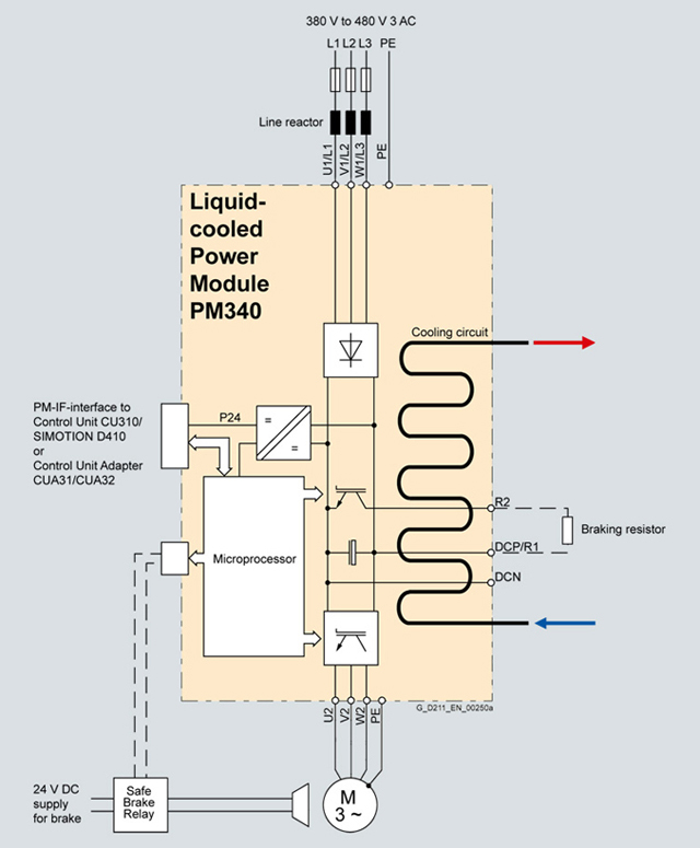
Connection example of a liquid-cooled PM340 Power Module
| Код | Заказной номер | Описание | Вес (кг) | Заказать |
|---|---|---|---|---|
| 116034 | 6SL3215-1SE23-8UA0 | sinamics s120 силовой модуль pm340 вход: 3ac 380-480в, 50/60гц выход: 3ac 178a (90квт) исполнение: блочный формат габарита типоразмер d водяное охлаждение | 15.9 | Заказать |
| 116035 | 6SL3215-1SE26-0UA0 | sinamics s120 силовой модуль pm340 вход: 3ac 380-480в, 50/60гц выход: 3ac 60a (30квт) исполнение: блочный формат типоразмер d водяное охлаждение | 15.9 | Заказать |
| 116036 | 6SL3215-1SE27-5UA0 | sinamics s120 силовой модуль pm340 вход: 3ac 380-480в, 50/60гц выход: 3ac 75a (37квт) исполнение: блочный формат типоразмер e водяное охлаждение | 19.8 | Заказать |
| 116037 | 6SL3215-1SE31-0UA0 | sinamics s120 силовой модуль pm340 вход: 3ac 380-480в, 50/60гц выход: 3ac 90a (45квт) исполнение: блочный формат типоразмер e водяное охлаждение | 19.8 | Заказать |
| 67951 | 6SL3215-1SE31-1UA0 | sinamics s120 силовой модуль pm340 вход: 3ac 380-480в, 50/60гц выход: 3ac 110a (55квт) исполнение: блочный формат типоразмер f водяное охлаждение | 50.7 | Заказать |
| 116038 | 6SL3215-1SE31-8UA0 | sinamics s120 силовой модуль pm340 вход: 3ac 380-480в, 50/60гц выход: 3ac 178a (90квт) исполнение: блочный формат типоразмер f водяное охлаждение | 50.7 | Заказать |
