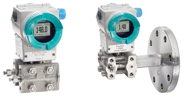
SITRANS P500 series pressure transmitters are digital pressure transmitters featuring extensive user-friendliness and which fulfill the most stringent demands of accuracy, long-term stability, speed and lots more.
Their extensive functionality allows you to set the pressure transmitter specifically to meet the requirements of your application. Despite their many settings options, operation on-site is easy. A multi-lingual menu with clear text instructions guides you through the process. There are also help texts available.
The innovative EDD with integrated QuickStart assistance is also quick and easy to parameterize by computer over the HART protocol.
Extensive diagnostic functions, e. g. slave pointer for pressure and temperature, or limit value indicator, make sure you always have the process under control. You can also display additional process values in measurement mode such as temperature or static pressure. The simultaneous display of volume is also easy.
SITRANS P500 series pressure transmitters can be parameterized to measure:
- Differential pressure
- Level
- Volume
- Mass
- volume flow
- Mass flow
SITRANS P500 series pressure transmitters can be used in industrial areas with extreme chemical and mechanical loads. Electromagnetic compatibility in the range 10 kHz to 1 GHz makes them suitable for locations with high electromagnetic emissions.
Pressure transmitters with type of protection "Intrinsic safety" and "Explosion-proof" may be installed within potentially explosive atmospheres (zone 1) or in zone 0. The pressure transmitter comes with a CE-declaration of conformity and fulfils the corresponding unified European directives (ATEX).
Pressure transmitters with the type of protection "Intrinsic safety" for use in zone 0 may be operated with power supply units of category "ia" and "ib".
By fitting a new measuring cell, it is possible to work with media temperatures of -40 to 125 °C (-40 to +257 °F) without the use of a remote seal.
The transmitters can be equipped with various designs of remote seals for special applications such as the measurement of highly viscous substances.
The pressure transmitter can be fully parameterized locally via the three operating keys and externally via HART.
Pressure transmitters for differential pressure and flow
- Measured variables:
- Differential pressure
- Small positive or negative pressure
- Flow q ~ √Δp (together with a primary differential pressure device (see Chapter "Flow Meters"))
- Span (infinitely adjustable)
for SITRANS P500 HART: 1.25 to 1250 mbar (0.018 to 18 psi)
Pressure transmitters for level
- Measured variable: Level of aggressive and non-aggressive liquids in open and closed vessels.
- Span (infinitely adjustable)
for SITRANS P500: 1.25 to 1250 mbar (0.018 to 18 psi) - Nominal diameter of the mounting flange
- DN 50 / PN 40
- DN 80 / PN 40
- DN 100/ PN 16, PN 40
- 2 inch/class 150, class 300
- 3 inch/class 150, class 300
- 4 inch/ class 150, class 300
- customized special version
In the case of level measurements in open containers, the low-pressure connection of the measuring cell remains open (measurement "compared to atmospheric").
In the case of measurements in closed containers, the lower-pressure connection has to be connected to the container in order to compensate the static pressure.
The wetted parts are made from a variety of materials, depending on the degree of corrosion resistance required.
- High measuring accuracy
- Very fast response time
- Extremely good long-term stability
- High reliability even under extreme chemical and mechanical loads
- For aggressive and non-aggressive gases, vapors and liquids
- Extensive diagnosis and simulation functions which can be used both on site as well as via HART.
- Optional separate replacement of measuring cell and electronics without recalibration.
- Extremely low conformity error values
- Infinitely adjustable spans of 1.25 to 1250 mbar (0.018 to 18 psi)
- Extremely good total performance and conformity error values with no loss of performance up to a turndown of 10 guaranteed.
- Additional integrated sensor for static pressure
- Parameterization via on-site control keys or HART
- Short process flanges nable space-saving installation.

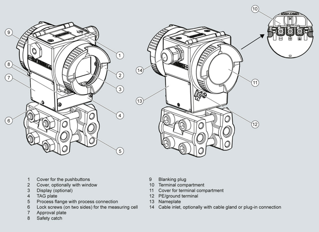
View of transmitter
- The electronics casing is made of painted die-cast aluminum.
- The casing has round screw-fastened covers front and back.
- Depending on the design the front covers is fitted with an inspection window. You can read off the measured value directly from the optional display through the inspection window.
- The inlet to the electrical junction box is located either on the left or right side. The unused opening in each case is sealed by a blanking plug.
- The PE/ground terminal is on the back of the housing.
- Access electrical junction box for auxiliary power and shielding by unscrewing the cover.
- Beneath the electronic housing is the measuring cell with its process flanges at which the process connections are available. The modular design of the pressure transmitter lets you swap the measuring cell, electronics and connection board as required.
- On the top of the housing you can see the screw fastened cover for the three keys for on-site operation of the transmitter.
Operation of electronics with HART

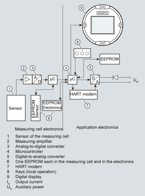
Function diagram of electronics
- The input pressure is converted into an electrical signal by the sensor.
- This signal is amplified by the measuring amplifier and digitalized in an analog-to-digital converter.
- The digital signal is analyzed in a microcontroller and corrected according to linearity and thermal characteristics.
- In a digital-to-analog converter it is then converted into the output current of 4 - 20 mA. When connected to supply lines, a diode circuit provides reverse polarity protection.
- The measuring cell-specific data, the electronic data and the parameterization data is held in two EEPROMs. One EEPROM is incorporated into the measuring cell electronics, the other is incorporated into the application electronics.
Operation
- The three keys enable you both to navigate and carry out parameterization and to visually track messages and process values, provided a display is available.
- If you have a device without a display, you can carry out zero adjustment using the keys. It is possible to retrofit a display at any time.
- You can also carry out settings by computer via a HART modem.
Mode of operation of the measuring cells
Measuring cell for differential pressure and flow

Measuring cell for differential pressure and flow, function diagram
- The differential pressure is transmitted via the seal diagrams and the filling liquid to the silicon pressure sensor.
- If the measuring limits are exceeded, the overload diaphragm flexes until it makes contact with the body of the measuring cell. This protects the sensor model from overload.
- The differential pressure causes the measuring diaphragm of the silicon pressure sensor to flex.
- The displacement changes the resistance value of the 4 piezo resistors in the measuring diaphragm in a bridge circuit.
- The change in the resistance causes a bridge output voltage proportional to the input pressure.
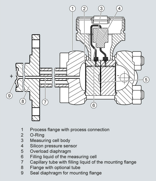
Measuring cell for level

Measuring cell for level, function diagram
- The input pressure (hydrostatic pressure) acts hydraulically on the measuring cell via the seal diaphragm on the mounting flange.
- The differential pressure applied to the measuring cell is transmitted via the seal diaphragm and the filling liquid to the silicon pressure sensor.
- If the measuring limits are exceeded, the overload diaphragm flexes until it makes contact with the body of the measuring cell. This protects the silicon pressure sensor from overload.
- The differential pressure causes the measuring diaphragm of the silicon pressure sensor to flex.
- The displacement changes the resistance value of the 4 piezo resistors in the measuring diaphragm in a bridge circuit.
- The change in the resistance causes a differential pressure proportional to the input pressure.
Parameterization of SITRANS P500 HART
Depending on the version, there are a range of options for parameterizing the pressure transmitter and for setting or scanning the parameters.
Parameterization using the input keys (local operation)
You can parameterize the transmitter in situ using the three keys provided a display is available. If you have no display, you can only carry out zero adjustment.
It is possible to retrofit a display. See accessories.
Parameterization using HART
Parameterization using HART is carried out using a HART Communicator or a PC in conjunction with a HART modem.

Communication between a HART Communicator and a pressure transmitter
When parameterizing with the HART Communicator, the connection is made directly to the 2-wire cable.

HART communication between a PC communicator and a pressure transmitter
For parameterizing via PC a HART modem is used which connects the transmitter to the PC.
The signals needed for communication in conformity with the HART 6.0 protocols are superimposed on the output current using the Frequency Shift Keying (FSK) method.
The necessary device files are available for download on the Internet.
SITRANS P500 parameterization options
The transmission offers you full parameterizing options both via HART as well as in situ provided the optional display is available.
For simple parameterizing we also offer the easy to understand QuickStart function with guided commissioning.
SITRANS P500 diagnostic functions
- Maintenance timer
- Slave pointer (can be reset/cannot be reset)
- Pressure (incl. time and temperature)
- Static pressure (incl. time and temperature)
- Sensor temperature (incl. time stamp)
- Electronic temperature (incl. time stamp)
- Limit transmitter
- Diagnostics warning
- Diagnostics alarm
- Simulation functions
- Display of trends and histograms
- Operating hours meter
Physical dimensions available for the SITRANS P500 HART display
Physical variable | Physical dimensions |
Pressure (setting can also be made in the factory) | Pa, MPa, kPa, bar, mbar, torr, atm, psi, g/cm2, kg/cm2, mmH2O (4 °C), inH2O (4 °C), inH2O (20 °C), mmH2O, mmH2O (4 °C), ftH2O (20 °C), inHg, mmHg, hPA |
Level (height data) | m, cm, mm, ft, in |
Volume | m3, dm3, hl, yd3, ft3, in3, gallon, lmp. gallon, bushel, barrel, barrel liquid, I; Norm (Standard) I; Norm (Standard) m3, Norm (Standard) feet3 |
Mass | g, kg, t (metric), lb, Ston, Lton, oz |
Volume flow | m3/d, m3/h, m3/s, l/min, l/s, ft3/d, ft3/min, ft3/s, US gallon/min, gallon/s, l/h, milL/d, gallon/d, gallon/h, milgallon/d, lmp.gallon/s, Imp.gallon/m, Imp.gallon/h, lmp.gallon/d, Norm (Standard) m3/h, Norm (Standard) l/h, Norm (Standard) ft3/h, Norm (Standard) ft3/m, barrel liquid/s, barrel liquid/m, barrel liquid/h |
Mass flow | t/d, t/h, t/min, kg/d, kg/h, kg/min, kg/s, g/h, g/min, g/s, lb/d, lb/min, lb/s, LTon/d, LTon/h, STon/d, STon/h, STon/min |
Temperature | °C, °F |
Miscellaneous | %, mA |


