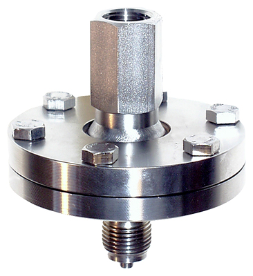
Diaphragm seal, screwed gland design with inside diaphragm for gauge, absolute and differential pressure for direct mounting
Diaphragm seal, screwed gland with inside diaphragm | |
Process connection | Nominal pressure |
| PN 100, PN 250 |
| PN 100, PN 250 |
| |
| PN 10 ... PN 40 |
| Class 150, class 300 |
Sealing face for open measurement flange | |
| To EN 1092-1, form B1 or ASME B16.5 RF 125 ... 250 AA |
Materials | |
| Stainless steel, Mat. No. 1.4404/316L |
| Stainless steel, Mat. No. 1.4404/316L |
| |
| |
Monel 400, mat. no. 2.4360 | |
Hastelloy C276, mat. no. 2.4819 | |
Hastelloy C4, mat. no. 2.4610 | |
Tantalum | |
| Stainless steel, Mat. no. 1.4404/316L |
| Stainless steel 1.4571/316Ti |
| Viton or copper (in the case of vacuum-free version) |
| Viton (FKM) (standard) |
Capillary | |
| Max. 10 m (32.8 ft) |
| 2 mm (0.079 inch) |
| 150 mm (5.9 inch) |
Filling liquid | |
(for remote seals of sandwich and flange design) |
|
| |
| |
| |
| |
Max. recommended process temperature | 170 °C (338 °F) |
Permissible ambient temperature | Dependent on the pressure transmitter and the filling liquid of the remote seal More information can be found in the technical specifications of the pressure transmitters and in the section "Technical data of filling liquid" in the introduction to the remote seals |
Weight | Approx. 1,5 kg (3.3 lb) |
Certificates and approvals | |
Classification according to pressure equipment directive (PED 97/23/EC) | For gases of fluid group 1 and liquids of fluid group 1; complies with requirements of article 3, paragraph 3 (sound engineering practice) |

Diaphragm seal, screwed gland with inside diaphragm, for gauge and absolute pressure, direct and attached directly to the transmitter with with capillaries, measurements in mm (Inch)
Range | D | L | b1 | Number of screws |
|---|---|---|---|---|
mm (inch) | mm (inch) | mm (inch) | ||
up to 100 bar | 98 | 14 | 16 | 6 |
up to 250 bar | 98 | 14 | 20 | 12 |

Diaphragm seal, screwed gland with inside diaphragm, for differential pressure, direct and attached directly to the transmitter with with capillaries, measurements in mm (Inch)
Nominal diameter | Nominal pressure | D | d4 | k | M | Number of holes | L | b1 |
|---|---|---|---|---|---|---|---|---|
mm (inch) | mm (inch) | mm (inch) | mm (inch) | mm (inch) | ||||
DN 25 | PN 10 ... 40 | 115 | 68 | 85 | M12 | 4 | 26 | 12 |
1 inch | 150 lb/sq.in | 108 | 50,8 | 79,2 | M12 | 4 | 22 | 12 |
1 inch | 300 lb/sq.in | 124 | 50,8 | 88,9 | M16 | 4 | 22 | 12 |