
SIMOREG CCP
The Converter Commutation Protector SIMOREG CCP is used to protect line-commutated SINAMICS DC MASTER converters in inverter operation against inverter commutation faults.
For line-commutated inverters, an appropriate line-side counter voltage is required in order to commutate the current between the individual power semiconductors. Commutation can be prevented from being completed (commutation fault) as a result of uncontrolled switching operations, line supply dips (weak line supplies, thunderstorms, etc.). As a result, in the regenerative feedback direction, a high current flows through the line supply or a cross-current in the converter. This can result in fuses blowing or under certain circumstances can destroy the semiconductors.
The software of the SINAMICS DC MASTER identifies if inverter commutation faults are pending and then issues the command to turn off the power semiconductors in the converter to the SIMOREG CCP. SIMOREG CCP then turns off the power semiconductors, ensures that the conditions to reduce the current in the motor are present and absorbs the magnetic energy stored in the motor as electric energy.
SIMOREG CCP limits the current that flows when inverter commutation faults occur to a non-hazardous value so that the thyristors and the associated super-fast fuses are protected. This eliminates the complex and time consuming replacement of fuses after inverter commutation faults.
Although inverter commutation faults cannot be prevented, their effects can be.
6RA7085-6FC00-0 | 6RA7091-6FC00-0 | 6RA7095-6FC00-0 | 6RA7090-6KC00-0 | 6RA7095-6KC00-0 | ||
|---|---|---|---|---|---|---|
Rated voltage | V | 460 (+15 %/-20 %) | 690 (+10 %/-20 %) | |||
Rated current | A | 600 | 1 200 | 2 000 | 1 000 | 2 000 |
Current range that can be covered 1) | A | up to 600 | up to 1 200 | up to 2 000 | up to 1 000 | up to 2 000 |
Rated supply voltage, electronics power supply | V | 380 (-20 %) … 60 V (+15 %) 2 AC; In = 1 A or | ||||
Rated frequency | Hz | 45 ... 65 | ||||
Power loss | W | 100 | ||||
Ambient temperature | ||||||
| °C | 0 ... 55 | ||||
| °C | -25 ... +70 | ||||
Installation altitude above sea level | m | ≤ 1 000 m | ||||
Climate class | 3K3 acc. to EN 60721-3-3 | |||||
Degree of pollution | 2 acc. to EN 50178 2) | |||||
Degree of protection | IP00 acc. to EN 60529 | |||||
Dimensions | ||||||
| mm | 406 | ||||
| mm | 780 | ||||
| mm | 500 | ||||
Weight, approx. | kg | 35 | 35 | 55 | 45 | 75 |
Fuse for connections 1U1, 1V1, 1W1 and 1D1 | 3NA3365-6 | 3NA3365-6 | 3NA3365-6 | 3NA3365-6 | 3NA3365-6 | |
Fuse for connections 2U1, 2V1, 2W1 | DIAZED 5SD604 | |||||
1) The current range that can be covered corresponds to the actual rated current of the SINAMICS DC MASTER. When the rated current is reduced (via parameter) then the lower value obtained applies. This means that for a SINAMICS DC MASTER with (according to the type plate) a rated current higher than 2 000 A (necessary e.g. to maintain longer specified overload times), it is possible to use the CCP if the actual rated current, specified by the parameterization, does not exceed 2 000 A. The possible overload capability of 1.8x the actual rated current can be additionally utilized.
2) Definition of pollution degree 2:
Generally only non-conductive pollution occurs. However, occasionally conductive pollution can be expected for a short period of time if the electronic equipment is not operational.
General technical data | ||||
|---|---|---|---|---|
Relevant standards | ||||
EN 50178 | Electronic equipment for use in power installations | |||
EN 50274 | Low-voltage switchgear and controlgear assemblies: Protection against electric shock – Protection against unintentional direct contact with hazardous live parts | |||
EN 60146-1-1 | Semiconductor converters: General requirements and line-commutated converters; specification of basic requirements | |||
EN 61800-1 | Adjustable speed electrical power drive systems, Part 1 – (DC drives) General requirements - Rating specifications for low-voltage DC power drive systems | |||
EN 61800-3 | Adjustable speed electrical power drive systems, Part 3 – EMC product standard including specific test methods | |||
EN 61800-5-1 | Adjustable speed electrical power drive systems – Part 5-1: Requirements regarding safety – electrical, thermal, and energy requirements | |||
IEC 62103 (identical to EN 50178) | Electronic equipment for use in power installations | |||
UBC 97 | Uniform Building Code | |||
Mechanical strength | Storage | Transport | Operation | |
Vibratory load | 1M2 acc. to EN 60721-3-1 | 2M2 acc. to EN 60721-3-2 | Constant deflection: | |
Shock load | 1M2 acc. to EN 60721-3-1 | 2M2 acc. to EN 60721-3-2 | 100 m/s2 at 11 ms (testing and measuring techniques acc. to EN 60068-2-27, Ea) | |
Approvals | ||||
UL/cUL | UL file No.: E145153 | |||
UL 508 C (UL Standard for Power Conversion Equipment), certification of the units up to and including 575 V | ||||
GOST | ||||
SIMOREG CCP distinguishes itself as a result of the compact and space-saving design.
The line supply voltage, line current as well as the armature voltage are continually sensed in the SINAMICS DC MASTER.
A possible commutation fault (inverter commutation fault - inverter shoot-through) is detected from these quantities, which results in the following measures being initiated:
1. The firing pulses are immediately disabled in the SINAMICS DC MASTER
2. The converter sends a "turn-off command" to SIMOREG CCP (via the serial interface).
3. SIMOREG CCP turns off the thyristors by connecting the pre-charged quenching capacitors anti-parallel to all thyristors. As a consequence, the current commutates from the converter into SIMOREG CCP. The quenching capacitors are initially discharged by the currents that they accept and they are then charged with the reverse polarity. The armature current starts to decrease as soon as the voltage of the quenching capacitors has reached the value of the motor EMF. However, the armature voltage continues to increase. As soon as it has reached the limit value, resistors are switched-in, which absorb the energy fed back from the motor during the remaining time of the current reduction phase.
4. A fault message is initiated in the SINAMICS DC MASTER.
5. The SIMOREG CCP re-charges the quenching capacitors with the reverse polarity so that a new quenching operation is possible.
Each time that the line supply voltage is switched in (e.g. via a line contactor), SIMOREG CCP requires approximately 3 s until it is ready for use as the quenching capacitors must first be charged up.
After a quenching operation, SIMOREG CCP requires a certain time until it is ready for use again. The duration depends on the operations during the quenching process and immediately afterwards. On one hand, the quenching capacitors in SIMOREG CCP must be charged to the required value with the reverse polarity (approx. 10 s). On the other hand, the chopper resistors, that convert the energy into heat when the armature current is reduced, require a cooling time calculated using a algorithm in the software. Depending on the amount of energy that was dissipated, this can take up to approx. 20 min.
SINAMICS DC MASTER has setting and monitoring parameters for commissioning, operation, monitoring and diagnostics of the SIMOREG CCP. The state of the SIMOREG CCP is signaled via connectors and the triggering of the SIMOREG CCP or erroneous states are signaled using fault and alarm messages.
Data is exchanged between the SINAMICS DC MASTER and SIMOREG CCP via the serial interface.
The following table lists the SIMOREG CCP units that are suitable for the particular SINAMICS DC MASTER.
This information is based on the rated unit data (taking into consideration the particular limit values) of the components and on the other hand, typical rated data for Siemens DC motors from Catalog DA 12 • 2008.
Note:
For plant and system configurations with reduced rated values (e.g. DC rating, US rating, voltage derating), under certain circumstances, suitable combinations of units can be found that are not listed in the table.
For detailed engineering and when selecting the appropriate CCP, our technical support personnel can provide you with help through the local Siemens office. Please specify the following plant or system data:
SINAMICS DC MASTER | SIMOREG CCP | ||||
|---|---|---|---|---|---|
Type | Rated DC voltage | Rated DC current | Type | Rated voltage | Rated current |
V | A | V | A | ||
6RA8078-6DV62-0AA0 | 420 | 280 | 6RA7085-6FC00-0 | 460 V 3 AC | DC 600 |
6RA8081-6DV62-0AA0 | 400 | ||||
6RA8085-6DV62-0AA0 | 600 | ||||
6RA8078-6FV62-0AA0 | 480 | 280 | |||
6RA8082-6FV62-0AA0 | 450 | ||||
6RA8085-6FV62-0AA0 | 600 | ||||
6RA8085-6DV62-0AA0 | 420 | 600 | 6RA7091-6FC00-0 | DC 1 200 | |
6RA8087-6DV62-0AA0 | 850 | ||||
6RA8091-6DV62-0AA0 | 1 200 | ||||
6RA8085-6FV62-0AA0 | 480 | 600 | |||
6RA8087-6FV62-0AA0 | 850 | ||||
6RA8091-6FV62-0AA0 | 1 200 | ||||
6RA8091-6DV62-0AA0 | 420 | 1 200 | 6RA7095-6FC00-0 | DC 2 000 | |
6RA8093-4DV62-0AA0 | 1 600 | ||||
6RA8095-4DV62-0AA0 | 2 000 | ||||
6RA8081-6GV62-0AA0 | 600 | 400 | 6RA7090-6KC00-0 | 690 V 3 AC | DC 1 000 |
6RA8085-6GV62-0AA0 | 600 | ||||
6RA8087-6GV62-0AA0 | 850 | ||||
6RA8086-6KV62-0AA0 | 725 | 760 | |||
6RA8090-6KV62-0AA0 | 1 000 | ||||
6RA8090-6GV62-0AA0 | 600 | 1 100 | 6RA7095-6KC00-0 | DC 2 000 | |
6RA8093-4GV62-0AA0 | 1 600 | ||||
6RA8095-4GV62-0AA0 | 2 000 | ||||
6RA8090-6KV62-0AA0 | 725 | 1 000 | |||
6RA8093-4KV62-0AA0 | 1 500 | ||||
6RA8095-4KV62-0AA0 | 2 000 | ||||

Block diagram
Operation without a main contactor is not permissible.
The control voltage for the main contactor (or the circuit-breaker) must always be routed via terminal XR (connection 109 and 110) of the SINAMICS DC MASTER unit and via terminal X_Contactor (connections 4 and 5) of the SIMOREG CCP.
For applications with SIMOREG CCP, in the case of a fault, the converter or SIMOREG CCP must be able to disconnect safely the arrangement from the line supply. Further, it must be ensured that the total of the delay times of all of the switching elements in the control circuit must not exceed the time set using the corresponding parameters. When SINAMICS DC MASTER units are connected in parallel, each unit is directly connected to a SIMOREG CCP in parallel (refer to the block diagram for the parallel connection).
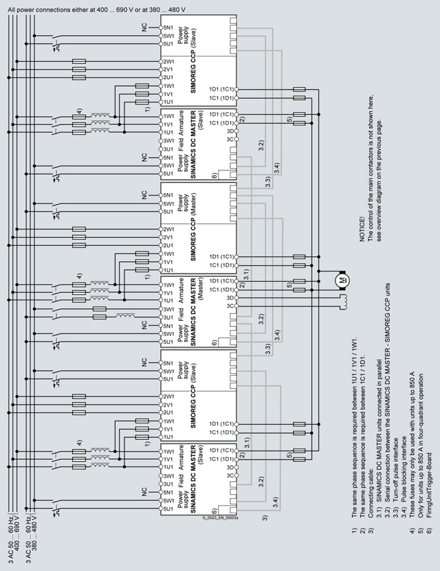
Block diagram for the parallel connection
Description | Order No. |
|---|---|
Operating Instructions in printed form | |
| 6RX1700‑0DD74 (from Edition 04) |
| 6RX1700‑0DD83 (from Edition 04) |
Operating Instructions English, French, German, Italian, Spanish, Russian 1) | 6RX1800‑0AD64 |
Patch cable UTP CAT5 Parallel patch cable for SINAMICS DC MASTER and SIMOREG CCP, approx. 5 m, | 6RY1707‑0AA08 |
FiringUnitTrigger Board | 6RY1803‑0CP00 |
1) However Russian not for SIMOREG CCP.
| Код | Заказной номер | Описание | Вес (кг) | Заказать |
|---|---|---|---|---|
| 114781 | 6RA7085-6FC00-0 | блок защиты преобразователя ccp-6ra70 600a/460v c98130-a7046-a5 | 35 | Заказать |
| 66733 | 6RA7090-6KC00-0 | блок защиты преобразователя ccp-6ra70 1000a/690v c98130-a7046-a2 | 45 | Заказать |
| 114795 | 6RA7091-6FC00-0 | блок защиты преобразователя ccp-6ra70 1200a/460v c98130-a7046-a4 | 35 | Заказать |
| 66744 | 6RA7095-6FC00-0 | блок защиты преобразователя ccp-6ra70 2000a/460v c98130-a7046-a3 | 55 | Заказать |
| 114811 | 6RA7095-6KC00-0 | блок защиты преобразователя ccp-6ra70 2000a/690v c98130-a7046-a1 | 75 | Заказать |
| 66844 | 6RX1700-0DD74 | инструкция по экспл. german,english | 0.088 | Заказать |
| 66845 | 6RX1700-0DD83 | инструкция по экспл. french italian, spanish | 1.2 | Заказать |
| 66846 | 6RX1800-0AD64 | operat.instr. german, english, french, spanish, italian, russian on dvd incl. starter | 0.05 | Заказать |
| 115053 | 6RY1707-0AA08 | кабель параллельного соединения для 6ra7 | 0.24 | Заказать |
| 115097 | 6RY1803-0CP00 | firingunittrigger-board c98043-a7103-l1 | 0.05 | Заказать |
