
The series of SINAMICS DC MASTER DC Converters includes:
General technical data | ||||
|---|---|---|---|---|
Relevant standards | ||||
EN 50178 | Electronic equipment for use in power installations | |||
EN 50274 | Low-voltage switchgear and controlgear assemblies: Protection against electric shock – Protection against unintentional direct contact with hazardous live parts | |||
EN 60146-1-1 | Semiconductor converters: General requirements and line-commutated converters; specification of basic requirements | |||
EN 61800-1 | Adjustable speed electrical power drive systems, Part 1 – (DC drives) General requirements - Rating specifications for low-voltage DC power drive systems | |||
EN 61800-3 | Adjustable speed electrical power drive systems, Part 3 – EMC product standard including specific test methods | |||
EN 61800-5-1 | Adjustable speed electrical power drive systems – Part 5-1: Requirements regarding safety – electrical, thermal, and energy requirements | |||
IEC 62103 (identical to EN 50178) | Electronic equipment for use in power installations | |||
UBC 97 | Uniform Building Code | |||
Electrical specifications | ||||
Overvoltage category | Category II acc. to EN 61800-5-1 within the line supply circuits | |||
Overvoltage strength | Class 1 acc. to EN 50178 | |||
Radio interference suppression | No radio interference suppression according to EN 61800-3 | |||
Mechanical data | ||||
Degree of protection | IP00 acc. to EN 60529; IP20 with accessories "Mounting kit to upgrade to IP20" for units up to 850 A | |||
Protection class | Class 1 acc. to EN 61140 | |||
Cooling method | ||||
| Self-ventilated | |||
| Forced-air cooling with integrated fan | |||
Closed-loop control stability | ||||
| Δn = 0.006 % of the rated motor speed | |||
| Δn = 0.1 % of the rated motor speed | |||
MTBF | > 170 000 h | |||
Environmental conditions | ||||
Permissible ambient temperature during storage and transport | -40 ... +70 °C | |||
Permissible humidity | Relative humidity ≤ 95 % (75 % at 17 °C average annual value, 95 % at 24 °C max., condensation not permissible) | |||
Climate class | 3K3 acc. to EN 60721-3-3 | |||
Insulation | Pollution degree 2 according to EN 61800-5-1 | |||
Installation altitude | ≤ 1 000 m above sea level (100 % load capability) | |||
Mechanical strength | Storage | Transport | Operation | |
Vibratory load | 1M2 acc. to EN 60721-3-1 | 2M2 acc. to EN 60721-3-2 | Constant deflection: | |
Shock load | 1M2 acc. to EN 60721-3-1 | 2M2 acc. to EN 60721-3-2 | 100 m/s2 at 11 ms (testing and measuring techniques acc. to EN 60068-2-27, Ea) | |
Approvals | ||||
UL/cUL | UL file No.: E203250 | |||
UL 508 C | Certification of the units up to and including 575 V | |||
GOST | ||||
Lloyd´s Register | In order to maintain the important limit values for marine certification, radio interference suppression filters should be used (see "Accessories and supplementary components") and option M08 should be selected (coated PCBs). | |||
Det Norske Veritas | ||||
American Bureau of Shipping | ||||
Germanische Lloyd | ||||
1) Conditions:
The closed-loop control (PI control) stability is referred to the rated motor speed and applies when the SINAMICS DC MASTER is in the warm operating condition. This is based on the following preconditions:
|
| Type | ||||
|---|---|---|---|---|---|---|
|
| 6RA8025-6DS22-0AA0 | 6RA8028-6DS22-0AA0 | 6RA8031-6DS22-0AA0 | 6RA8075-6DS22-0AA0 | 6RA8078-6DS22-0AA0 |
Rated armature supply voltage 1) | V | 400 V 3 AC | ||||
Rated armature input current | A | 50 | 75 | 104 | 174 | 232 |
Rated supply voltage, electronics power supply | V | 380 (-25 %) … 480 V (+10 %) 2 AC; In = 1 A or | ||||
Rated fan supply voltage | V | Self-ventilated | 24 V DC internal | |||
Rated fan current | A | Internal supply | ||||
Air flow | m3/h | 300 | ||||
Sound pressure level 2) | dB (A) | 52.4 | ||||
Rated field supply voltage 1) | V | 400 V 2 AC | ||||
Rated frequency | Hz | 45 … 65 | ||||
Rated DC voltage 1) | V | 485 | ||||
Rated DC current | A | 60 | 90 | 125 | 210 | 280 |
Overload capability | x × In | 1.8 | ||||
Rated power | kW | 29 | 44 | 61 | 102 | 136 |
Power loss at rated DC current | kW | 0.25 | 0.36 | 0.41 | 0.69 | 0.81 |
Rated DC field voltage 1) | V | max. 325 | ||||
Rated DC field current | A | 10 | 15 | |||
Normal ambient temperature in operation 5) | °C | 0 … +45 | 0 … +40 | |||
Storage and transport temperature | °C | -40 … +70 | ||||
Installation altitude above sea level 5) | ≤ 1 000 m for rated DC current | |||||
Dimensions | ||||||
| mm | 268 | ||||
| mm | 385 | ||||
| mm | 252 | ||||
Weight, approx. | kg | 10 | 14 | 15 | ||
Note:
Detailed dimension drawings in the PDF and DXF formats are available on the DVD-ROM supplied with Catalog D 23.1 and in the Internet under http://www.siemens.com/sinamics-dcm (information material).
Data for single-phase operation
|
| Type | ||||
|---|---|---|---|---|---|---|
|
| 6RA8025-6DS22-0AA0 | 6RA8028-6DS22-0AA0 | 6RA8031-6DS22-0AA0 | ||
Rated DC voltage | V | 320 | ||||
Rated DC current | A | 42.0 | 63.0 | 87.5 | ||
|
| Type | |||
|---|---|---|---|---|---|
|
| 6RA8081-6DS22-0AA0 | 6RA8085-6DS22-0AA0 | 6RA8087-6DS22-0AA0 | 6RA8091-6DS22-0AA0 |
Rated armature supply voltage 1) | V | 400 V 3 AC | |||
Rated armature input current | A | 332 | 498 | 706 | 996 |
Rated supply voltage, electronics power supply | V | 380 (-25 %) … 480 V (+10 %) 2 AC; In = 1 A or | |||
Rated fan supply voltage | V | 400 V 3 AC ± 10 % (50 Hz) | |||
Rated fan current | A | 0.23 3) | 0.3 3) | ||
Air flow | m3/h | 600 | 1 000 | ||
Sound pressure level 2) | dB (A) | 64.5 | |||
Rated field supply voltage 1) | V | 400 V 2 AC | 480 V 2 AC | ||
Rated frequency | Hz | 45 … 65 | |||
Rated DC voltage 1) | V | 485 | |||
Rated DC current | A | 400 | 600 | 850 | 1 200 |
Overload capability | x × In | 1.8 | |||
Rated power | kW | 194 | 291 | 412 | 582 |
Power loss at rated DC current | kW | 1.37 | 1.84 | 2.47 | 4.11 |
Rated DC field voltage 1) | V | max. 325 | max. 390 | ||
Rated DC field current | A | 25 | 30 | 40 | |
Normal ambient temperature in operation 5) | °C | 0 … +40 | |||
Storage and transport temperature | °C | -40 … +70 | |||
Installation altitude above sea level 5) | ≤ 1 000 m for rated DC current | ||||
Dimensions | |||||
| mm | 268 | |||
| mm | 625 | 700 | 783 | |
| mm | 275 | 311 | 435 | |
Weight, approx. | kg | 26 | 28 | 38 | 78 |
Note:
Detailed dimension drawings in the PDF and DXF formats are available on the DVD-ROM supplied with Catalog D 23.1 and in the Internet under http://www.siemens.com/sinamics-dcm (information material).
|
| Type | ||
|---|---|---|---|---|
|
| 6RA8093-4DS22-0AA0 | 6RA8095-4DS22-0AA0 | 6RA8098-4DS22-0AA0 |
Rated armature supply voltage 1) | V | 400 V 3 AC | 400 V 3 AC | |
Rated armature input current | A | 1 328 | 1 660 | 2 490 |
Rated supply voltage, electronics power supply | V | 380 (-25 %) … 480 V (+10 %) 2 AC; In = 1 A or | ||
Rated fan supply voltage | V | 400 V 3 AC ± 10 % (50 Hz) | ||
Rated fan current | A | 1 4) | ||
Air flow | m3/h | 2 400 | ||
Sound pressure level 2) | dB (A) | 75.6 | ||
Rated field supply voltage 1) | V | 480 V 2 AC | ||
Rated frequency | Hz | 45 … 65 | ||
Rated DC voltage 1) | V | 485 | ||
Rated DC current | A | 1 600 | 2 000 | 3 000 |
Overload capability | x × In | 1.8 | ||
Rated power | kW | 776 | 970 | 1 455 |
Power loss at rated DC current | kW | 5.68 | 6.78 | 10.64 |
Rated DC field voltage 1) | V | max. 390 | ||
Rated DC field current | A | 40 | ||
Normal ambient temperature in operation 5) | °C | 0 … +40 | ||
Storage and transport temperature | °C | -40 … +70 | ||
Installation altitude above sea level 5) | ≤ 1 000 m for rated DC current | |||
Dimensions | ||||
| mm | 453 | ||
| mm | 883 | ||
| mm | 505 | ||
Weight, approx. | kg | 135 | 165 | |
Note:
Detailed dimension drawings in the PDF and DXF formats are available on the DVD-ROM supplied with Catalog D 23.1 and in the Internet under http://www.siemens.com/sinamics-dcm (information material).
|
| Type | ||||
|---|---|---|---|---|---|---|
|
| 6RA8025-6FS22-0AA0 | 6RA8028-6FS22-0AA0 | 6RA8031-6FS22-0AA0 | 6RA8075-6FS22-0AA0 | 6RA8078-6FS22-0AA0 |
Rated armature supply voltage 1) | V | 480 V 3 AC | ||||
Rated armature input current | A | 50 | 75 | 104 | 174 | 232 |
Rated supply voltage, electronics power supply | V | 380 (-25 %) … 480 V (+10 %) 2 AC; In = 1 A or | ||||
Rated fan supply voltage | V | Self-ventilated | 24 V DC internal | |||
Rated fan current | A | Internal supply | ||||
Air flow | m3/h | 300 | ||||
Sound pressure level 2) | dB (A) | 52.4 | ||||
Rated field supply voltage 1) | V | 480 V 2 AC | ||||
Rated frequency | Hz | 45 … 65 | ||||
Rated DC voltage 1) | V | 575 | ||||
Rated DC current | A | 60 | 90 | 125 | 210 | 280 |
Overload capability | x × In | 1.8 | ||||
Rated power | kW | 35 | 52 | 72 | 121 | 161 |
Power loss at rated DC current | kW | 0.30 | 0.38 | 0.43 | 0.72 | 0.81 |
Rated DC field voltage 1) | V | max. 390 | ||||
Rated DC field current | A | 10 | 15 | |||
Normal ambient temperature in operation 5) | °C | 0 … +45 | 0 … +40 | |||
Storage and transport temperature | °C | -40 … +70 | ||||
Installation altitude above sea level 5) | ≤ 1 000 m for rated DC current | |||||
Dimensions | ||||||
| mm | 268 | ||||
| mm | 385 | ||||
| mm | 252 | ||||
Weight, approx. | kg | 11 | 14 | 15 | ||
Note:
Detailed dimension drawings in the PDF and DXF formats are available on the DVD-ROM supplied with Catalog D 23.1 and in the Internet under http://www.siemens.com/sinamics-dcm (information material).
Data for single-phase operation
|
| Type | ||||
|---|---|---|---|---|---|---|
|
| 6RA8025-6FS22-0AA0 | 6RA8028-6FS22-0AA0 | 6RA8031-6FS22-0AA0 | ||
Rated DC voltage | V | 385 | ||||
Rated DC current | A | 42.0 | 63.0 | 87.5 | ||
|
| Type | |||
|---|---|---|---|---|---|
|
| 6RA8082-6FS22-0AA0 | 6RA8085-6FS22-0AA0 | 6RA8087-6FS22-0AA0 | 6RA8091-6FS22-0AA0 |
Rated armature supply voltage 1) | V | 480 V 3 AC | |||
Rated armature input current | A | 374 | 498 | 706 | 996 |
Rated supply voltage, electronics power supply | V | 380 (-25 %) … 480 V (+10 %) 2 AC; In = 1 A or | |||
Rated fan supply voltage | V | 400 V 3 AC ± 10 % (50 Hz) | |||
Rated fan current | A | 0.23 3) | 0.3 3) | ||
Air flow | m3/h | 600 | 1 000 | ||
Sound pressure level 2) | dB (A) | 64.5 | |||
Rated field supply voltage 1) | V | 480 V 2 AC | |||
Rated frequency | Hz | 45 … 65 | |||
Rated DC voltage 1) | V | 575 | |||
Rated DC current | A | 450 | 600 | 850 | 1 200 |
Overload capability | x × In | 1.8 | |||
Rated power | kW | 259 | 345 | 489 | 690 |
Power loss at rated DC current | kW | 1.58 | 1.91 | 2.60 | 4.24 |
Rated DC field voltage 1) | V | max. 390 | |||
Rated DC field current | A | 25 | 30 | ||
Normal ambient temperature in operation 5) | °C | 0 … +40 | |||
Storage and transport temperature | °C | -40 … +70 | |||
Installation altitude above sea level 5) | ≤ 1 000 m for rated DC current | ||||
Dimensions | |||||
| mm | 268 | |||
| mm | 625 | 700 | 783 | |
| mm | 275 | 311 | 435 | |
Weight, approx. | kg | 28 | 38 | 78 | |
Note:
Detailed dimension drawings in the PDF and DXF formats are available on the DVD-ROM supplied with Catalog D 23.1 and in the Internet under http://www.siemens.com/sinamics-dcm (information material).
|
| Type | |||||
|---|---|---|---|---|---|---|---|
|
| 6RA8025-6GS22-0AA0 | 6RA8031-6GS22-0AA0 | 6RA8075-6GS22-0AA0 | 6RA8081-6GS22-0AA0 | 6RA8085-6GS22-0AA0 | 6RA8087-6GS22-0AA0 |
Rated armature supply voltage 1) | V | 575 V 3 AC | |||||
Rated armature input current | A | 50 | 104 | 174 | 332 | 498 | 664 |
Rated supply voltage, electronics power supply | V | 380 (-25 %) … 480 V (+10 %) 2 AC; In = 1 A or | |||||
Rated fan supply voltage | V | Self-ventilated | 24 V DC internal | 400 V 3 AC ± 10 % (50 Hz) | |||
Rated fan current | A | Internal supply | 0.23 3) | ||||
Air flow | m3/h | 300 | 600 | ||||
Sound pressure level 2) | dB (A) | 52.4 | 64.5 | ||||
Rated field supply voltage 1) | V | 480 V 2 AC | |||||
Rated frequency | Hz | 45 … 65 | |||||
Rated DC voltage 1) | V | 690 | |||||
Rated DC current | A | 60 | 125 | 210 | 400 | 600 | 800 |
Overload capability | x × In | 1.8 | |||||
Rated power | kW | 41 | 86 | 145 | 276 | 414 | 552 |
Power loss at rated DC current | kW | 0.27 | 0.46 | 0.74 | 1.60 | 2.00 | 2.69 |
Rated DC field voltage 1) | V | max. 390 | |||||
Rated DC field current | A | 10 | 15 | 25 | 30 | ||
Normal ambient temperature in operation 5) | °C | 0 … +45 | 0 … +40 | ||||
Storage and transport temperature | °C | -40 … +70 | |||||
Installation altitude above sea level 5) | ≤ 1 000 m for rated DC current | ||||||
Dimensions | |||||||
| mm | 268 | |||||
| mm | 385 | 625 | 700 | |||
| mm | 252 | 275 | 311 | |||
Weight, approx. | kg | 11 | 14 | 26 | 28 | 38 | |
Note:
Detailed dimension drawings in the PDF and DXF formats are available on the DVD-ROM supplied with Catalog D 23.1 and in the Internet under http://www.siemens.com/sinamics-dcm (information material).
Data for single-phase operation
|
| Type | |||||
|---|---|---|---|---|---|---|---|
|
| 6RA8025-6GS22-0AA0 | 6RA8031-6GS22-0AA0 | ||||
Rated DC voltage | V | 460 | |||||
Rated DC current | A | 42.0 | 87.5 | ||||
|
| Type | ||||
|---|---|---|---|---|---|---|
|
| 6RA8090-6GS22-0AA0 | 6RA8093-4GS22-0AA0 | 6RA8095-4GS22-0AA0 | 6RA8096-4GS22-0AA0 | 6RA8097-4GS22-0AA0 |
Rated armature supply voltage 1) | V | 575 V 3 AC | ||||
Rated armature input current | A | 913 | 1 328 | 1 660 | 1 826 | 2 324 |
Rated supply voltage, electronics power supply | V | 380 (-25 %) … 480 V (+10 %) 2 AC; In = 1 A or | ||||
Rated fan supply voltage | V | 400 V 3 AC ± 10 % (50 Hz) | ||||
Rated fan current | A | 0.3 3) | 1 4) | |||
Air flow | m3/h | 1 000 | 2 400 | |||
Sound pressure level 2) | dB (A) | 64.5 | 75.6 | |||
Rated field supply voltage 1) | V | 480 V 2 AC | ||||
Rated frequency | Hz | 45 … 65 | ||||
Rated DC voltage 1) | V | 690 | ||||
Rated DC current | A | 1 100 | 1 600 | 2 000 | 2 200 | 2 800 |
Overload capability | x × In | 1.8 | ||||
Rated power | kW | 759 | 1 104 | 1 380 | 1 518 | 1 932 |
Power loss at rated DC current | kW | 4.02 | 6.04 | 7.07 | 7.39 | 10.53 |
Rated DC field voltage 1) | V | max. 390 | ||||
Rated DC field current | A | 40 | ||||
Normal ambient temperature in operation 5) | °C | 0 … +40 | ||||
Storage and transport temperature | °C | -40 … +70 | ||||
Installation altitude above sea level 5) | ≤ 1 000 m for rated DC current | |||||
Dimensions | ||||||
| mm | 268 | 453 | |||
| mm | 785 | 883 | |||
| mm | 435 | 505 | |||
Weight, approx. | kg | 78 | 135 | 165 | ||
Note:
Detailed dimension drawings in the PDF and DXF formats are available on the DVD-ROM supplied with Catalog D 23.1 and in the Internet under http://www.siemens.com/sinamics-dcm (information material).
|
| Type | ||||
|---|---|---|---|---|---|---|
|
| 6RA8086-6KS22-0AA0 | 6RA8090-6KS22-0AA0 | 6RA8093-4KS22-0AA0 | 6RA8095-4KS22-0AA0 | 6RA8097-4KS22-0AA0 |
Rated armature supply voltage 1) | V | 690 V 3 AC | ||||
Rated armature input current | A | 598 | 830 | 1 245 | 1 660 | 2 158 |
Rated supply voltage, electronics power supply | V | 380 (-25 %) … 480 V (+10 %) 2 AC; In = 1 A or | ||||
Rated fan supply voltage | V | 400 V 3 AC ± 10 % (50 Hz) | ||||
Rated fan current | A | 0.23 3) | 0.3 3) | 1 4) | ||
Air flow | m3/h | 600 | 1 000 | 2 400 | ||
Sound pressure level 2) | dB (A) | 64.5 | 75.6 | |||
Rated field supply voltage 1) | V | 480 V 2 AC | ||||
Rated frequency | Hz | 45 … 65 | ||||
Rated DC voltage 1) | V | 830 | ||||
Rated DC current | A | 720 | 1 000 | 1 500 | 2 000 | 2 600 |
Overload capability | x × In | 1.8 | ||||
Rated power | kW | 598 | 830 | 1 245 | 1 660 | 2 158 |
Power loss at rated DC current | kW | 2.77 | 3.96 | 6.67 | 8.16 | 10.30 |
Rated DC field voltage 1) | V | max. 390 | ||||
Rated DC field current | A | 30 | 40 | |||
Normal ambient temperature in operation 5) | °C | 0 … +40 | ||||
Storage and transport temperature | °C | -40 … +70 | ||||
Installation altitude above sea level 5) | ≤ 1 000 m for rated DC current | |||||
Dimensions | ||||||
| mm | 268 | 453 | |||
| mm | 700 | 785 | 883 | ||
| mm | 311 | 435 | 505 | ||
Weight, approx. | kg | 38 | 78 | 135 | 165 | |
Note:
Detailed dimension drawings in the PDF and DXF formats are available on the DVD-ROM supplied with Catalog D 23.1 and in the Internet under http://www.siemens.com/sinamics-dcm (information material).
|
| Type | |||
|---|---|---|---|---|---|
|
| 6RA8088-6LS22-0AA0 | 6RA8093-4LS22-0AA0 | 6RA8095-4LS22-0AA0 | 6RA8096-4MS22-0AA0 |
Rated armature supply voltage 1) | V | 830 V 3 AC | 950 V 3 AC | ||
Rated armature input current | A | 789 | 1 245 | 1 577 | 1 826 |
Rated supply voltage, electronics power supply | V | 380 (-25 %) … 480 V (+10 %) 2 AC; In = 1 A or | |||
Rated fan supply voltage | V | 400 V 3 AC ± 10 % (50 Hz) | |||
Rated fan current | A | 0.3 3) | 1 4) | ||
Air flow | m3/h | 1 000 | 2 400 | ||
Sound pressure level 2) | dB (A) | 64.5 | 75.6 | ||
Rated field supply voltage 1) | V | 480 V 2 AC | |||
Rated frequency | Hz | 45 … 65 | |||
Rated DC voltage 1) | V | 1 000 | 1 140 | ||
Rated DC current | A | 950 | 1 500 | 1 900 | 2 200 |
Overload capability | x × In | 1.8 | |||
Rated power | kW | 950 | 1 500 | 1 900 | 2 508 |
Power loss at rated DC current | kW | 4.22 | 7.12 | 8.67 | 11.34 |
Rated DC field voltage 1) | V | max. 390 | |||
Rated DC field current | A | 40 | |||
Normal ambient temperature in operation 5) | °C | 0 … +40 | |||
Storage and transport temperature | °C | -40 … +70 | |||
Installation altitude above sea level 5) | ≤ 1 000 m for rated DC current | ||||
Dimensions | |||||
| mm | 268 | 453 | ||
| mm | 785 | 883 | ||
| mm | 435 | 505 | ||
Weight, approx. | kg | 78 | 135 | 165 | |
Note:
Detailed dimension drawings in the PDF and DXF formats are available on the DVD-ROM supplied with Catalog D 23.1 and in the Internet under http://www.siemens.com/sinamics-dcm (information material).
|
| Type | ||||
|---|---|---|---|---|---|---|
|
| 6RA8013-6DV62-0AA0 | 6RA8018-6DV62-0AA0 | 6RA8025-6DV62-0AA0 | 6RA8028-6DV62-0AA0 | 6RA8031-6DV62-0AA0 |
Rated armature supply voltage 1) | V | 400 V 3 AC | ||||
Rated armature input current | A | 12 | 25 | 50 | 75 | 104 |
Rated supply voltage, electronics power supply | V | 380 (-25 %) … 480 V (+10 %) 2 AC; In = 1 A or | ||||
Rated fan supply voltage | V | Self-ventilated | ||||
Rated fan current | A | |||||
Air flow | m3/h | |||||
Sound pressure level 2) | dB (A) | |||||
Rated field supply voltage 1) | V | 400 V 2 AC | ||||
Rated frequency | Hz | 45 … 65 | ||||
Rated DC voltage 1) | V | 420 | ||||
Rated DC current | A | 15 | 30 | 60 | 90 | 125 |
Overload capability | x × In | 1.8 | ||||
Rated power | kW | 6.3 | 12.6 | 25 | 38 | 53 |
Power loss at rated DC current | kW | 0.13 | 0.18 | 0.25 | 0.32 | 0.41 |
Rated DC field voltage 1) | V | max. 325 | ||||
Rated DC field current | A | 3 | 5 | 10 | ||
Normal ambient temperature in operation 5) | °C | 0 … +45 | ||||
Storage and transport temperature | °C | -40 … +70 | ||||
Installation altitude above sea level 5) | ≤ 1 000 m for rated DC current | |||||
Dimensions | ||||||
| mm | 268 | ||||
| mm | 385 | ||||
| mm | 221 | 252 | |||
Weight, approx. | kg | 11 | 14 | |||
Note:
Detailed dimension drawings in the PDF and DXF formats are available on the DVD-ROM supplied with Catalog D 23.1 and in the Internet under http://www.siemens.com/sinamics-dcm (information material).
Data for single-phase operation
|
| Type | ||||
|---|---|---|---|---|---|---|
|
| 6RA8013-6DV62-0AA0 | 6RA8018-6DV62-0AA0 | 6RA8025-6DV62-0AA0 | 6RA8028-6DV62-0AA0 | 6RA8031-6DV62-0AA0 |
Rated DC voltage | V | 280 | ||||
Rated DC current | A | 10.5 | 21.0 | 42.0 | 63.0 | 87.5 |
|
| Type | ||||
|---|---|---|---|---|---|---|
|
| 6RA8075-6DV62-0AA0 | 6RA8078-6DV62-0AA0 | 6RA8081-6DV62-0AA0 | 6RA8085-6DV62-0AA0 | 6RA8087-6DV62-0AA0 |
Rated armature supply voltage 1) | V | 400 V 3 AC | ||||
Rated armature input current | A | 174 | 232 | 332 | 498 | 706 |
Rated supply voltage, electronics power supply | V | 380 (-25 %) … 480 V (+10 %) 2 AC; In = 1 A or | ||||
Rated fan supply voltage | V | 24 V DC internal | 400 V 3 AC ± 10 % (50 Hz) | |||
Rated fan current | A | Internal supply | 0.23 3) | |||
Air flow | m3/h | 300 | 600 | |||
Sound pressure level 2) | dB (A) | 52.4 | 64.5 | |||
Rated field supply voltage 1) | V | 400 V 2 AC | ||||
Rated frequency | Hz | 45 … 65 | ||||
Rated DC voltage 1) | V | 420 | ||||
Rated DC current | A | 210 | 280 | 400 | 600 | 850 |
Overload capability | x × In | 1.8 | ||||
Rated power | kW | 88 | 118 | 168 | 252 | 357 |
Power loss at rated DC current | kW | 0.69 | 0.81 | 1.37 | 1.84 | 2.47 |
Rated DC field voltage 1) | V | max. 325 | ||||
Rated DC field current | A | 15 | 25 | 30 | ||
Normal ambient temperature in operation 5) | °C | 0 … +40 | ||||
Storage and transport temperature | °C | -40 … +70 | ||||
Installation altitude above sea level 5) | ≤ 1 000 m for rated DC current | |||||
Dimensions | ||||||
| mm | 268 | ||||
| mm | 385 | 625 | 700 | ||
| mm | 252 | 275 | 311 | ||
Weight, approx. | kg | 15 | 26 | 31 | 42 | |
Note:
Detailed dimension drawings in the PDF and DXF formats are available on the DVD-ROM supplied with Catalog D 23.1 and in the Internet under http://www.siemens.com/sinamics-dcm (information material).
|
| Type | |||
|---|---|---|---|---|---|
|
| 6RA8091-6DV62-0AA0 | 6RA8093-4DV62-0AA0 | 6RA8095-4DV62-0AA0 | 6RA8098-4DV62-0AA0 |
Rated armature supply voltage 1) | V | 400 V 3 AC | 400 V 3 AC | ||
Rated armature input current | A | 996 | 1 328 | 1 660 | 2 490 |
Rated supply voltage, electronics power supply | V | 380 (-25 %) … 480 V (+10 %) 2 AC; In = 1 A or | |||
Rated fan supply voltage | V | 400 V 3 AC ± 10 % (50 Hz) | |||
Rated fan current | A | 0.3 3) | 1 4) | ||
Air flow | m3/h | 1 000 | 2 400 | ||
Sound pressure level 2) | dB (A) | 64.5 | 75.6 | ||
Rated field supply voltage 1) | V | 480 V 2 AC | |||
Rated frequency | Hz | 45 … 65 | |||
Rated DC voltage 1) | V | 420 | |||
Rated DC current | A | 1 200 | 1 600 | 2 000 | 3 000 |
Overload capability | x × In | 1.8 | |||
Rated power | kW | 504 | 672 | 840 | 1 260 |
Power loss at rated DC current | kW | 4.11 | 5.68 | 6.78 | 10.64 |
Rated DC field voltage 1) | V | max. 390 | |||
Rated DC field current | A | 40 | |||
Normal ambient temperature in operation 5) | °C | 0 … +40 | |||
Storage and transport temperature | °C | -40 … +70 | |||
Installation altitude above sea level 5) | ≤ 1 000 m for rated DC current | ||||
Dimensions | |||||
| mm | 268 | 453 | ||
| mm | 785 | 883 | ||
| mm | 435 | 505 | ||
Weight, approx. | kg | 78 | 155 | 185 | |
Note:
Detailed dimension drawings in the PDF and DXF formats are available on the DVD-ROM supplied with Catalog D 23.1 and in the Internet under http://www.siemens.com/sinamics-dcm (information material).
|
| Type | ||||||
|---|---|---|---|---|---|---|---|---|
|
| 6RA8013-6FV62-0AA0 | 6RA8018-6FV62-0AA0 | 6RA8025-6FV62-0AA0 | 6RA8028-6FV62-0AA0 | 6RA8031-6FV62-0AA0 | 6RA8075-6FV62-0AA0 | |
Rated armature supply voltage 1) | V | 480 V 3 AC | 480 V 3 AC | |||||
Rated armature input current | A | 12 | 25 | 50 | 75 | 104 | 174 | |
Rated supply voltage, electronics power supply | V | 380 (-25 %) … 480 V (+10 %) 2 AC; In = 1 A or | ||||||
Rated fan supply voltage | V | Self-ventilated | 24 V DC internal | |||||
Rated fan current | A | Internal supply | ||||||
Air flow | m3/h | 300 | ||||||
Sound pressure level 2) | dB (A) | 52.4 | ||||||
Rated field supply voltage 1) | V | 480 V 2 AC | ||||||
Rated frequency | Hz | 45 … 65 | ||||||
Rated DC voltage 1) | V | 500 | ||||||
Rated DC current | A | 15 | 30 | 60 | 90 | 125 | 210 | |
Overload capability | x × In | 1.8 | ||||||
Rated power | kW | 6 | 15 | 30 | 45 | 63 | 105 | |
Power loss at rated DC current | kW | 0.13 | 0.19 | 0.30 | 0.34 | 0.43 | 0.72 | |
Rated DC field voltage 1) | V | max. 390 | ||||||
Rated DC field current | A | 3 | 5 | 10 | 10 | 10 | 15 | |
Normal ambient temperature in operation 5) | °C | 0 … +45 | 0 … +40 | |||||
Storage and transport temperature | °C | -40 … +70 | ||||||
Installation altitude above sea level 5) | ≤ 1 000 m for rated DC current | |||||||
Dimensions | ||||||||
| mm | 268 | ||||||
| mm | 385 | ||||||
| mm | 221 | 252 | |||||
Weight, approx. | kg | 11 | 14 | 15 | ||||
Note:
Detailed dimension drawings in the PDF and DXF formats are available on the DVD-ROM supplied with Catalog D 23.1 and in the Internet under http://www.siemens.com/sinamics-dcm (information material).
Data for single-phase operation
|
| Type | |||||
|---|---|---|---|---|---|---|---|
|
| 6RA8013-6FV62-0AA0 | 6RA8018-6FV62-0AA0 | 6RA8025-6FV62-0AA0 | 6RA8028-6FV62-0AA0 | 6RA8031-6FV62-0AA0 | |
Rated DC voltage | V | 335 | |||||
Rated DC current | A | 10.5 | 21.0 | 42.0 | 63.0 | 87.5 | |
|
| Type | ||||
|---|---|---|---|---|---|---|
|
| 6RA8078-6FV62-0AA0 | 6RA8082-6FV62-0AA0 | 6RA8085-6FV62-0AA0 | 6RA8087-6FV62-0AA0 | 6RA8091-6FV62-0AA0 |
Rated armature supply voltage 1) | V | 480 V 3 AC | ||||
Rated armature input current | A | 232 | 374 | 498 | 706 | 996 |
Rated supply voltage, electronics power supply | V | 380 (-25 %) … 480 V (+10 %) 2 AC; In = 1 A or | ||||
Rated fan supply voltage | V | 24 V DC internal | 400 V 3 AC ± 10 % (50 Hz) | |||
Rated fan current | A | Internal supply | 0.23 3) | 0.3 3) | ||
Air flow | m3/h | 300 | 600 | 1 000 | ||
Sound pressure level 2) | dB (A) | 52.4 | 64.5 | |||
Rated field supply voltage 1) | V | 480 V 2 AC | ||||
Rated frequency | Hz | 45 … 65 | ||||
Rated DC voltage 1) | V | 500 | ||||
Rated DC current | A | 280 | 450 | 600 | 850 | 1 200 |
Overload capability | x × In | 1.8 | ||||
Rated power | kW | 140 | 225 | 300 | 425 | 600 |
Power loss at rated DC current | kW | 0.81 | 1.58 | 1.91 | 2.60 | 4.24 |
Rated DC field voltage 1) | V | max. 390 | ||||
Rated DC field current | A | 15 | 25 | 25 | 30 | 40 |
Normal ambient temperature in operation 5) | °C | 0 … +40 | ||||
Storage and transport temperature | °C | -40 … +70 | ||||
Installation altitude above sea level 5) | ≤ 1 000 m for rated DC current | |||||
Dimensions | ||||||
| mm | 268 | ||||
| mm | 385 | 625 | 700 | 785 | |
| mm | 252 | 275 | 311 | 435 | |
Weight, approx. | kg | 15 | 31 | 42 | 78 | |
Note:
Detailed dimension drawings in the PDF and DXF formats are available on the DVD-ROM supplied with Catalog D 23.1 and in the Internet under http://www.siemens.com/sinamics-dcm (information material).
|
| Type | |||||
|---|---|---|---|---|---|---|---|
|
| 6RA8025-6GV62-0AA0 | 6RA8031-6GV62-0AA0 | 6RA8075-6GV62-0AA0 | 6RA8081-6GV62-0AA0 | 6RA8085-6GV62-0AA0 | 6RA8087-6GV62-0AA0 |
Rated armature supply voltage 1) | V | 575 V 3 AC | |||||
Rated armature input current | A | 50 | 104 | 174 | 332 | 498 | 706 |
Rated supply voltage, electronics power supply | V | 380 (-25 %) … 480 V (+10 %) 2 AC; In = 1 A or | |||||
Rated fan supply voltage | V | Self-ventilated | 24 V DC internal | 400 V 3 AC ± 10 % (50 Hz) | |||
Rated fan current | A | Internal supply | 0.23 3) | ||||
Air flow | m3/h | 300 | 600 | ||||
Sound pressure level 2) | dB (A) | 52.4 | 64.5 | ||||
Rated field supply voltage 1) | V | 480 V 2 AC | |||||
Rated frequency | Hz | 45 … 65 | |||||
Rated DC voltage 1) | V | 600 | |||||
Rated DC current | A | 60 | 125 | 210 | 400 | 600 | 850 |
Overload capability | x × In | 1.8 | |||||
Rated power | kW | 36 | 75 | 126 | 240 | 360 | 510 |
Power loss at rated DC current | kW | 0.27 | 0.46 | 0.74 | 1.60 | 2.00 | 2.83 |
Rated DC field voltage 1) | V | max. 390 | |||||
Rated DC field current | A | 10 | 10 | 15 | 25 | 25 | 30 |
Normal ambient temperature in operation 5) | °C | 0 … +45 | 0 … +40 | ||||
Storage and transport temperature | °C | -40 … +70 | |||||
Installation altitude above sea level 5) | ≤ 1 000 m for rated DC current | ||||||
Dimensions | |||||||
| mm | 268 | |||||
| mm | 385 | 65 | 700 | |||
| mm | 252 | 275 | 311 | |||
Weight, approx. | kg | 11 | 14 | 15 | 26 | 31 | 42 |
Note:
Detailed dimension drawings in the PDF and DXF formats are available on the DVD-ROM supplied with Catalog D 23.1 and in the Internet under http://www.siemens.com/sinamics-dcm (information material).
Data for single-phase operation
|
| Type | |||||
|---|---|---|---|---|---|---|---|
|
| 6RA8025-6GV62-0AA0 | 6RA8031-6GV62-0AA0 | ||||
Rated DC voltage | V | 400 | |||||
Rated DC current | A | 42.0 | 87.5 | ||||
|
| Type | ||||
|---|---|---|---|---|---|---|
|
| 6RA8090-6GV62-0AA0 | 6RA8093-4GV62-0AA0 | 6RA8095-4GV62-0AA0 | 6RA8096-4GV62-0AA0 | 6RA8097-4GV62-0AA0 |
Rated armature supply voltage 1) | V | 575 V 3 AC | ||||
Rated armature input current | A | 913 | 1 328 | 1 660 | 1 826 | 2 324 |
Rated supply voltage, electronics power supply | V | 380 (-25 %) … 480 V (+10 %) 2 AC; In = 1 A or | ||||
Rated fan supply voltage | V | 400 V 3 AC ± 10 % (50 Hz) | ||||
Rated fan current | A | 0.3 3) | 1 4) | |||
Air flow | m3/h | 1 000 | 2 400 | |||
Sound pressure level 2) | dB (A) | 64.5 | 75.6 | |||
Rated field supply voltage 1) | V | 480 V 2 AC | ||||
Rated frequency | Hz | 45 … 65 | ||||
Rated DC voltage 1) | V | 600 | ||||
Rated DC current | A | 1 100 | 1 600 | 2 000 | 2 200 | 2 800 |
Overload capability | x × In | 1.8 | ||||
Rated power | kW | 660 | 960 | 1 200 | 1 320 | 1 680 |
Power loss at rated DC current | kW | 4.02 | 6.04 | 7.07 | 7.39 | 10.53 |
Rated DC field voltage 1) | V | max. 390 | ||||
Rated DC field current | A | 40 | ||||
Normal ambient temperature in operation 5) | °C | 0 … +40 | ||||
Storage and transport temperature | °C | -40 … +70 | ||||
Installation altitude above sea level 5) | ≤ 1 000 m for rated DC current | |||||
Dimensions | ||||||
| mm | 268 | 453 | |||
| mm | 785 | 883 | |||
| mm | 435 | 505 | |||
Weight, approx. | kg | 78 | 155 | 185 | ||
Note:
Detailed dimension drawings in the PDF and DXF formats are available on the DVD-ROM supplied with Catalog D 23.1 and in the Internet under http://www.siemens.com/sinamics-dcm (information material).
|
| Type | ||||
|---|---|---|---|---|---|---|
|
| 6RA8086-6KV62-0AA0 | 6RA8090-6KV62-0AA0 | 6RA8093-4KV62-0AA0 | 6RA8095-4KV62-0AA0 | 6RA8097-4KV62-0AA0 |
Rated armature supply voltage 1) | V | 690 V 3 AC | ||||
Rated armature input current | A | 631 | 830 | 1 245 | 1 660 | 2 158 |
Rated supply voltage, electronics power supply | V | 380 (-25 %) … 480 V (+10 %) 2 AC; In = 1 A or | ||||
Rated fan supply voltage | V | 400 V 3 AC ± 10 % (50 Hz) | ||||
Rated fan current | A | 0.23 3) | 0.3 3) | 1 4) | ||
Air flow | m3/h | 600 | 1 000 | 2 400 | ||
Sound pressure level 2) | dB (A) | 64.5 | 75.6 | |||
Rated field supply voltage 1) | V | 480 V 2 AC | ||||
Rated frequency | Hz | 45 … 65 | ||||
Rated DC voltage 1) | V | 725 | ||||
Rated DC current | A | 760 | 1 000 | 1 500 | 2 000 | 2 600 |
Overload capability | x × In | 1.8 | ||||
Rated power | kW | 551 | 725 | 1 088 | 1 450 | 1 885 |
Power loss at rated DC current | kW | 2.90 | 3.96 | 6.67 | 8.16 | 10.30 |
Rated DC field voltage 1) | V | max. 390 | ||||
Rated DC field current | A | 30 | 40 | |||
Normal ambient temperature in operation 5) | °C | 0 … +40 | ||||
Storage and transport temperature | °C | -40 … +70 | ||||
Installation altitude above sea level 5) | ≤ 1 000 m for rated DC current | |||||
Dimensions | ||||||
| mm | 268 | 453 | |||
| mm | 700 | 785 | 883 | ||
| mm | 311 | 435 | 505 | ||
Weight, approx. | kg | 42 | 78 | 155 | 185 | |
Note:
Detailed dimension drawings in the PDF and DXF formats are available on the DVD-ROM supplied with Catalog D 23.1 and in the Internet under http://www.siemens.com/sinamics-dcm (information material).
|
| Type | |||
|---|---|---|---|---|---|
|
| 6RA8088-6LV62-0AA0 | 6RA8093-4LV62-0AA0 | 6RA8095-4LV62-0AA0 | 6RA8096-4MV62-0AA0 |
Rated armature supply voltage 1) | V | 830 V 3 AC | 950 V 3 AC | ||
Rated armature input current | A | 789 | 1 245 | 1 577 | 1 826 |
Rated supply voltage, electronics power supply | V | 380 (-25 %) … 480 V (+10 %) 2 AC; In = 1 A or | |||
Rated fan supply voltage | V | 400 V 3 AC ± 10 % (50 Hz) | |||
Rated fan current | A | 0.3 3) | 1 4) | ||
Air flow | m3/h | 1 000 | 2 400 | ||
Sound pressure level 2) | dB (A) | 64.5 | 75.6 | ||
Rated field supply voltage 1) | V | 480 V 2 AC | |||
Rated frequency | Hz | 45 … 65 | |||
Rated DC voltage 1) | V | 875 | 1 000 | ||
Rated DC current | A | 950 | 1 500 | 1 900 | 2 200 |
Overload capability | x × In | 1.8 | |||
Rated power | kW | 831 | 1 313 | 1 663 | 2 200 |
Power loss at rated DC current | kW | 4.22 | 7.12 | 8.67 | 11.34 |
Rated DC field voltage 1) | V | max. 390 | |||
Rated DC field current | A | 40 | |||
Normal ambient temperature in operation 5) | °C | 0 … +40 | |||
Storage and transport temperature | °C | -40 … +70 | |||
Installation altitude above sea level 5) | ≤ 1 000 m for rated DC current | ||||
Dimensions | |||||
| mm | 268 | 453 | ||
| mm | 785 | 883 | ||
| mm | 435 | 505 | ||
Weight, approx. | kg | 78 | 155 | 185 | |
Note:
Detailed dimension drawings in the PDF and DXF formats are available on the DVD-ROM supplied with Catalog D 23.1 and in the Internet under http://www.siemens.com/sinamics-dcm (information material).
1) The armature/field supply voltage may be lower than the rated armature/field voltage (set via parameter; in the case of units with a 400 V rated voltage, an input voltage of up to 85 V is permitted). The output voltage decreases accordingly. The specified DC output voltage can be maintained up to an undervoltage of 5 % of the line supply voltage (rated armature/field supply voltage).
2) Fan noise for a unit installed in an IP20 electrical cabinet (door closed, 50 Hz operation or operation at 24 V DC for units with an internal supply)
3) For fan motor type R2D220-AB02-19 in units 6RA8081, 6RA8085, and 6RA8087 with a rated voltage of 400 V or 575 V, UL systems require a Siemens motor circuit-breaker of type 3RV1011-0DA1 or 3RV1011-0EA1, set to 0.3 A.
4) For fan motor type RH28M-2DK.3F.1R in units 6RA8090, 6RA8091, 6RA8093, and 6RA8095 with a rated voltage of 400 V or 575 V, UL systems require a Siemens motor circuit-breaker of type 3RV1011-0KA1 or 3RV1011-1AA1, set to 1.25 A.
5) Derating factors for higher temperatures and installation altitudes, see „Current derating“.
Note:
When ordering a unit with options, add the suffix "-Z" after the Order No. and then state the order code(s) for the desired option(s) after the suffix.
Example:
6RA8075-6GV62-0AA0-Z
G00+G20+L85+...
See also ordering examples.
The following table provides an overview of the available options. Detailed descriptions of the options are provided in the section "Description of options".
|
|
| Order No. for separate order |
|
|---|---|---|---|---|
Designation | Order code | Notes | not coated | coated |
CUD | ||||
Standard CUD left | (Standard) | – | 6RY1803‑0AA00 | 6RY1803‑0AA20 |
Advanced CUD left | G00 | – | 6RY1803‑0AA05 | 6RY1803‑0AA25 |
Standard CUD right | G10 | This option requires an Advanced CUD left – order code G00 | 6RY1803‑0AA00 + | 6RY1803‑0AA20 + |
Advanced CUD right | G11 | This option requires an Advanced CUD left – order code G00 | 6RY1803‑0AA05 + | 6RY1803‑0AA25 + |
Communication Board CBE20 left | G20 | This option requires an Advanced CUD left – order code G00 | – | 6SL3055-0AA00-2EB0 |
Communication Board CBE20 right | G21 | This option requires an Advanced CUD right – order code G11 | – | 6SL3055-0AA00-2EB0 |
Memory card left | S01 | – | 6RX1800-0AS01 | – |
Memory card right | S02 | This option requires a Standard CUD right – order code G10 – or an Advanced CUD right – order code G11 | 6RX1800-0AS01 | – |
Field | ||||
Field power section 1Q | (Standard) | – | – 1) | – 1) |
Field power section 2Q | L11 | Only applicable for units from 60 to 3 000 A | – 1) | – 1) |
Without field power section | L10 | Only applicable for units from 60 to 3 000 A | – | – |
85 A field power section | L85 | Only applicable for units from 1 500 to 3 000 A | – 1) | – 1) |
Fans | ||||
Standard fan | (Standard) | Self-ventilated units do not have a fan | – 1) | – |
Fans for single-phase connection | L21 | Only applicable for units from 400 to 1 200 A | – 1) | – |
Additional options | ||||
Electronics power supply for connection to 24 V DC | L05 | Standard for Control Module, input voltage range 18 to 30 V, current consumption 5 A at 24 V | – 1) | – 1) |
Armature supply with extra-low voltage 10 to 50 V | L04 | Only applicable for units up to ≤ 575 V rated supply voltage | – 1) | – 1) |
Coated PCBs | M08 | – | – | – |
Nickel-plated copper busbars | M10 | Only applicable for units from 60 to 3 000 A | – | – |
External sensor for ambient or inlet temperature | L15 | Only applicable for units from 1 500 to 3 000 A | – 1) | – |
1) Available as spare part.
G00 | G10 | G11 | G20 | G21 | L04 | L05 | L10 | L11 | L15 | L21 | L85 | M08 | M10 | S01 | S02 | |
|---|---|---|---|---|---|---|---|---|---|---|---|---|---|---|---|---|
G00 | ✓ | ✓ | ✓ | ✓ | ✓ | ✓ | ✓ | ✓ | ✓ | ✓ | ✓ | ✓ | ✓ | ✓ | ✓ | |
G10 | ✓ | – | ✓ | – | ✓ | ✓ | ✓ | ✓ | ✓ | ✓ | ✓ | ✓ | ✓ | ✓ | ✓ | |
G11 | ✓ | – | ✓ | ✓ | ✓ | ✓ | ✓ | ✓ | ✓ | ✓ | ✓ | ✓ | ✓ | ✓ | ✓ | |
G20 | ✓ | ✓ | ✓ | ✓ | ✓ | ✓ | ✓ | ✓ | ✓ | ✓ | ✓ | ✓ | ✓ | ✓ | ✓ | |
G21 | ✓ | – | ✓ | ✓ | ✓ | ✓ | ✓ | ✓ | ✓ | ✓ | ✓ | ✓ | ✓ | ✓ | ✓ | |
L04 | ✓ | ✓ | ✓ | ✓ | ✓ | ✓ | ✓ | ✓ | ✓ | ✓ | ✓ | ✓ | ✓ | ✓ | ✓ | |
L05 | ✓ | ✓ | ✓ | ✓ | ✓ | ✓ | ✓ | ✓ | ✓ | ✓ | ✓ | ✓ | ✓ | ✓ | ✓ | |
L10 | ✓ | ✓ | ✓ | ✓ | ✓ | ✓ | ✓ | – | ✓ | ✓ | – | ✓ | ✓ | ✓ | ✓ | |
L11 | ✓ | ✓ | ✓ | ✓ | ✓ | ✓ | ✓ | – | ✓ | ✓ | ✓ | ✓ | ✓ | ✓ | ✓ | |
L15 | ✓ | ✓ | ✓ | ✓ | ✓ | ✓ | ✓ | ✓ | ✓ | ✓ | ✓ | ✓ | ✓ | ✓ | ✓ | |
L21 | ✓ | ✓ | ✓ | ✓ | ✓ | ✓ | ✓ | ✓ | ✓ | ✓ | ✓ | ✓ | ✓ | ✓ | ✓ | |
L85 | ✓ | ✓ | ✓ | ✓ | ✓ | ✓ | ✓ | – | ✓ | ✓ | ✓ | ✓ | ✓ | ✓ | ✓ | |
M08 | ✓ | ✓ | ✓ | ✓ | ✓ | ✓ | ✓ | ✓ | ✓ | ✓ | ✓ | ✓ | ✓ | ✓ | ✓ | |
M10 | ✓ | ✓ | ✓ | ✓ | ✓ | ✓ | ✓ | ✓ | ✓ | ✓ | ✓ | ✓ | ✓ | ✓ | ✓ | |
S01 | ✓ | ✓ | ✓ | ✓ | ✓ | ✓ | ✓ | ✓ | ✓ | ✓ | ✓ | ✓ | ✓ | ✓ | ✓ | |
S02 | ✓ | ✓ | ✓ | ✓ | ✓ | ✓ | ✓ | ✓ | ✓ | ✓ | ✓ | ✓ | ✓ | ✓ | ✓ |
✓ | Option can be combined without any restrictions |
|---|---|
– | Option cannot be combined |
Example 1
Application:
A DC drive system is required for a cableway. A SINAMICS DC MASTER is to handle the closed-loop control of the selected 560 kW DC motor with a rated armature voltage of 420 V and a rated armature current of 1 306 A. Due to the overdimensioning of 25 % specified by the acceptance authorities, and due to the maximum ambient temperature of 45 °C that can occur, the rated current of the converter had to be further reduced by 5 %. This is the reason that a unit with a rated supply current of 2 000 A was selected. The converter capable of energy recovery is to be connected to a 400 V line supply. A PROFINET connection is required for the higher-level control.
Solution:
A four-quadrant converter with 2 000 A and 400 V AC should be selected for this application. The incremental encoder to sense the speed - mounted on the motor - is directly evaluated in the CUD of the SINAMICS DC MASTER, without requiring any additional option.
The following options must be selected in order to permit the PROFINET connection:
G00 (Advanced CUD left)
G20 (PROFINET Communication Board CBE20 left)
The ordering data are as follows:
6RA8095-4DV62-0AA0-Z
G00+G20
Example 2
Application:
An unwinder for paper in a reeler-slitter is to be modernized - but the existing motor is to be kept. The power section is to be supplied from the existing 690 V supply. The technological control is to be implemented in the higher-level PCS7 system. The client specified PROFIBUS as the control and setpoint interface. The following measured values and status displays are to be visualized in the cabinet doors of the drive cabinet to facilitate fast and simple diagnostics for the service and maintenance personnel: Armature current, armature voltage, speed, field current, status messages - operation and fault.
The customer explained that he repeatedly had problems with the existing converter relating to overvoltage in the motor armature circuit - and as a consequence, this resulted in tension fluctuations in the paper web when the motor went into the field-weakening range. As a result of instability in the control voltage supply, in the past, there were repeatedly failures that had a negative impact on the availability.
Solution:
As a result of the data of the existing motor and the customer specifications relating to acceleration and braking ramps, tambour roll weight and maximum diameter, a four-quadrant converter was selected with a rated supply voltage of 690 V and a rated current of 1 500 A. The dynamic overload capability of the units is utilized to brake the drive when the paper web breaks.
The technological control with current setpoint interface is realized in the higher-level control. This is the reason that for this particular application, the Standard CUD is sufficient, which already has an integrated Profibus interface.
The problem with armature overvoltages when entering the field weakening range has now been resolved by selecting the two-quadrant field power section option. By actively reducing the current using a counter-voltage, the field current actual value can now follow the field current setpoint - even for steep acceleration ramps - and therefore overvoltages are avoided in the armature circuit. The tension fluctuations in the paper web are consequentially eliminated.
Selecting the option “Electronics power supply for connection to 24 V DC” means that the drive system can be intergrated into a favorably-priced and low-maintenance DC UPS system comprising SITOP components.
The requirements regarding actual value and status displays were addressed by installing the AOP30 Advanced Operator Panel in the doors of the drive cabinet.
Coated PCBs and nickel-plated copper busbars were selected as a result of the aggressive atmosphere with a high percentage of H2S.
The availability of equipment is extremely important in the paper industry. This is the reason that the option "memory card left" was selected to allow service and maintenance personnel short repair times in the case of faults. Software and additional languages of the AOP text are saved on this card. Further, parameter values can be additionally saved there and there is a reserved memory range for offline long-time trace records.
The following options must be selected for this particular application:
L05 (electronics power supply for connection to 24 V DC)
L11 (2Q field power section)
M08 (coated PCBs)
M10 (nickel-plated copper busbars)
S01 (memory card left)
Further, the following accessories are required:
Advanced Operator Panel AOP30 (6SL3055-0AA00-4CA)
RS485 cable, 3 m long
The ordering data are as follows:
6RA8093-4KV62-0AA0-Z
L05+L11+M08+M10+S01
and
6SL3055-0AA00-4CA
as well as
6RY1807-0AP00
G00
Advanced CUD left
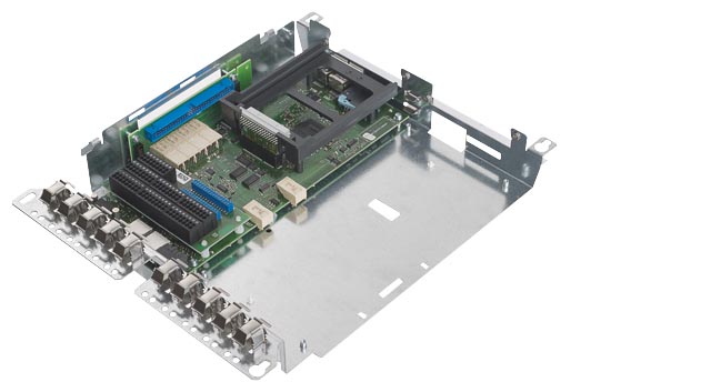
In addition to the connections and functions of the Standard CUD, the Advanced CUD has two DRIVE-CLiQ connections and one option slot. The use of an Advanced CUD also provides the opportunity of inserting an additional CUD (Standard or Advanced) to increase the computational performance and the number of terminals. This can be used, e.g. to implement additional technological functions.
By using an Advanced CUD, which is located in the lefthand slot instead of the Standard CUD, the SINAMICS SMC30, TM15, TM31 and CBE20 components can be connected to the SINAMICS DC MASTER. More detailed information on the SINAMICS components is available in the section "Accessories and supplementary components".
G10
Standard CUD right
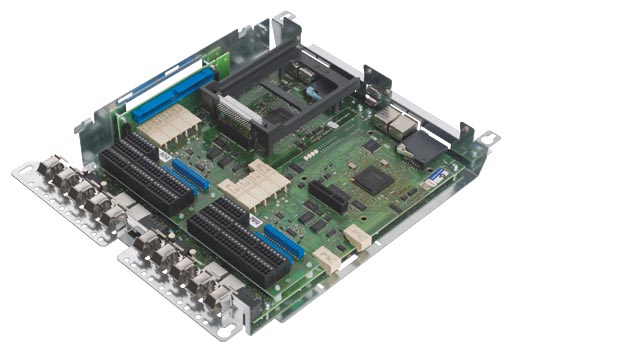
Selecting option G10 provides the possibility of further increasing the performance of technology functions for the SINAMICS DC MASTER. As a result of the additional Standard CUD that is inserted in the righthand slot of the electronics tray, users have additional computational performance at their fingertips in order to fulfill even the highest demands when it comes to closed-loop control performance. Option G00 is required when selecting option G10. An extension to include two Control Units is only possible when the Advanced CUD is inserted in the lefthand slot.
G11
Advanced CUD right
With option G11, users can address the highest demands regarding the closed-loop control performance and use the wide range of interfaces. With this option, in addition to the Advanced CUD located in the lefthand slot, an additional Advanced CUD can be mounted in the righthand slot. This therefore doubles the number of interfaces of the SINAMICS DC MASTER. Option G00 is required when selecting option G11. An extension to include two Control Units is only possible when the Advanced CUD is inserted in the lefthand slot.
G20
Communication Board CBE20 left

The CBE20 Communication Board can be used to connect to a PROFINET IO network via the Advanced CUD.
The SINAMICS DC MASTER then assumes the function of a PROFINET IO device in the sense of PROFINET and offers the following functions:
The CBE20 is inserted in the option slot of the Advanced CUD, which is inserted in the lefthand slot. An Advanced CUD must be located in the lefthand slot in order to be able to use option G20. This can be selected with option G00.
Technical data | |
|---|---|
Permissible ambient temperature | |
| -40 ... +70 °C |
| 0 ... 55 °C |
Approvals | cULus (File No.: E164110) |
Accessories for CBE20 | Type |
|---|---|
Industrial Ethernet FC | |
| 6GK1901-1BB30-0AA0 |
| 6GK1901-1BB30-0AB0 |
| 6GK1901-1GA00 |
| 6XV1840-2AH10 |
| 6XV1870-2B |
| 6XV1870-2D |
| 6XV1840-3AH10 |
| 6XV1840-4AH10 |
The cables are sold by the meter.
For further information about connectors and cables, refer to Catalog IK PI.
G21
Communication Board CBE20 right
With option G21, an Advanced CUD inserted in the righthand slot (refer to option G11) can be extended by the CBE20. More detailed information on the functionality, selection and ordering data of the CBE20 is available under option G20.
L04
Armature supply with extra-low voltage 10 to 50 V
With option L04, the SINAMICS DC MASTER is re-equipped for operation with 10 to 50 V AC. This is frequently required especially for electrochemical applications, when controlling solenoids, when using the converter to supply the fields of special motors or Ward-Leonard converters (MG sets).
This option can only be selected for units with rated supply voltages of up to 575 V.
L05
Electronics power supply for connection to 24 V DC
With option L05, users have the possibility of equipping SINAMICS DC MASTER with an electronics power supply for connection to 24 V DC instead of the standard electronics power supply. This option allows users to connect the units to a favorably-priced 24 V UPS system.
This option cannot be selected for Control Modules as the Control Module is supplied as standard with an electronics power supply for connection to 24 V DC.
Input voltage range: 18 to 30 V,
current consumption: 5 A at 24 V
L10
Without field power section
In some applications it may be necessary to individually adapt the field power section. For this particular case, users can order option L10 where SINAMICS DC MASTER is not equipped with the standard integrated field power section. This then allows them to implement their own individual solutions for the field power section.
This option cannot be ordered for units with rated DC currents from 15 to 30 A.
L11
2Q field power section
For applications that demand high speed field current changes, by specifying option L11, the SINAMICS DC MASTER can be equipped with a two-quadrant field with active current reduction. Further, this field power section has an integrated field overvoltage protection.
This option cannot be ordered for units with rated DC currents from 15 to 30 A.
L15
External sensor for ambient or inlet temperature
Option L15 is a sensor located outside the unit to measure the ambient or inlet temperature. For example, this can be used to simply monitor the cabinet temperature and/or identify when the air intake filter is blocked.
This option is only available for units with rated DC currents from 1 500 to 3 000 A.
L21
Fan for single-phase connection
A fan can be optionally supplied with a single-phase connection for units with rated DC currents between 400 and 1 200 A. This allows fans to be more quickly replaced than three-phase fans - especially as the direction of rotation does not have to be checked.
Units smaller than 400 A are self-ventilated or have an integrated 24 V DC fan. Units with ratings of greater than 1 200 A require a three-phase connection for the fan due to the higher power consumption.
Rated supply voltage: 230 V 1 AC ± 10% (50 and 60 Hz)
L85
85 A field power section
With option L85, users can have the SINAMICS DC MASTER equipped with a rated DC field current of 85 A.
This option can only be ordered for units with rated DC currents from 1 500 to 3 000 A.
M08
Coated PCBs
In order to improve the reliability for increased degrees of pollution and climatic stressing, it is possible to order PCBs of the SINAMICS DC MASTER that are coated on both sides by specifying option M08.
M10
Nickel-plated copper busbars
When ordered with Option M10, the SINAMICS DC MASTER is equipped with nickel-plated copper busbars. The degree of availability can be increased for aggressive atmospheres.
This option is not available for units with rated DC currents from 15 to 30 A.
S01
Memory card left
With option S01, users receive a memory card for one Standard CUD or one Advanced CUD, which is inserted in the lefthand slot.
This memory card offers the following options:
The SINAMICS Link function requires that the memory card is always inserted.
S02
Memory card right
With option S02, users receive a memory card for one Standard CUD or one Advanced CUD, which is inserted in the righthand slot.
This memory card offers the following options:
The SINAMICS Link function requires that the memory card is always inserted.
In order to be able to use option S02, a Standard CUD right (option G10) or an Advanced CUD right (option G11) is required.
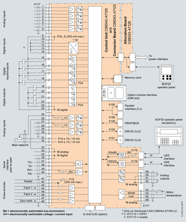
Connection diagram, Standard CUD/Advanced CUD with typical connections
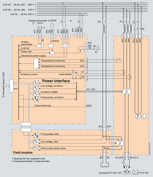
Connection diagram, DC Converters, 400 to 3 000 A, electronics power supply 400 V or 230 V, with fan
Overview
Overview of terminals and connectors
1U1, 1V1, 1W1, 1C1, 1D1 | Power section |
|---|---|
3U1, 3W1, 3C, 3D | Field circuit |
4U1, 4V1, 4W1, 4N1 | Fan |
5U1, 5W1, 5N1 | Electronics power supply |
X100, X101 | DRIVE-CLiQ |
X126 | PROFIBUS |
X165, X166 | Parallel connection interface |
X177 | Analog inputs, digital inputs, digital outputs, setpoints, reference voltage (P10/N10), serial interface (peer-to-peer), pulse encoder, analog outputs, temperature sensor |
X178 | RS485 interface for connection of the AOP30, alternatively USS interface; generally only one of the interfaces X178 or X179 can be used |
X179 | RS232 interface can be used as USS interface; generally only one of the interfaces X178 or X179 can be used |
XR1, XS1, XT1 | Relay output for line contactor, safety shutdown (E-STOP), analog tachometer |
Power section
Terminal type, power connections for 15 A and 30 A units
Type | KDS 10 PC board terminal |
|---|---|
Conductor size |
|
Stripped length | 12 mm |
Tightening torque | 1.2 … 1.5 Nm |
Terminal type, power connections for units of 60 A and higher
Units | Data |
|---|---|
60 … 210 A | 1U1, 1V1, 1W1: 3 × 20 mm aluminum busbar, through hole for M8 |
Max. conductor cross-section for cables with cable lug in acc. with DIN 46234: | |
Tightening torque for 1U1, 1V1, 1W1, 1C1, 1D1: 13 Nm | |
280 A | 1U1, 1V1, 1W1: 3 × 20 mm copper busbar, through hole for M8 |
Max. conductor cross-section for cables with cable lug in acc. with DIN 46234: | |
Tightening torque for 1U1, 1V1, 1W1, 1C1, 1D1: 13 Nm | |
400 … 450 A | 1U1, 1V1, 1W1: 5 × 30 mm aluminum busbar, through hole for M10 |
Max. conductor cross-section for cables with cable lug in acc. with DIN 46234: | |
Tightening torque for 1U1, 1V1, 1W1, 1C1, 1D1: 25 Nm | |
600 A | 1U1, 1V1, 1W1: 5 × 30 mm copper busbar, through hole for M10 |
Max. conductor cross-section for cables with cable lug in acc. with DIN 46234: | |
Tightening torque for 1U1, 1V1, 1W1, 1C1, 1D1: 25 Nm | |
720 … 850 A | 1U1, 1V1, 1W1, 1C1, 1D1: 5 × 60 mm copper busbar, through hole for M12 |
Max. conductor cross-section for cables with cable lug in acc. with DIN 46234: | |
Tightening torque for 1U1, 1V1, 1W1, 1C1, 1D1: 44 Nm | |
900 … 1 200 A | 1U1, 1V1, 1W1, 1C1, 1D1: 10 × 80 mm copper busbar, through hole for M12 |
Max. conductor cross-section for cables with cable lug in acc. with DIN 46234: | |
Tightening torque for 1U1, 1V1, 1W1, 1C1, 1D1: 44 Nm | |
1 500 … 2 000 A and | 1U1, 1V1, 1W1: 10 × 80 mm aluminum busbar, through hole for M12 |
Max. conductor cross-section for cables with cable lug in acc. with DIN 46234: | |
Tightening torque for 1U1, 1V1, 1W1, 1C1, 1D1: 44 Nm | |
2 200 A (> 575 V) … 3 000 A | 1U1, 1V1, 1W1: 2x 10 × 100 mm copper busbar, through hole for M12 |
Tightening torque for 1U1, 1V1, 1W1, 1C1, 1D1: 44 Nm | |
Protective conductor: | |
The units are designed for a permanent line supply connection in accordance with DIN VDE 0160‑106, Section 6.5.2.1.
The conductor cross-sections must be determined in accordance with the regulations that apply in each case – e.g. DIN VDE 0276‑1000.
Assignment of power connections
Terminal | Function | Technical data |
|---|---|---|
1U1 | Line input armature power section | See under "Technical specifications" (Rated armature supply voltage) |
 | Protective conductor PE | |
1C1 (1D1) | Motor connection armature circuit | See under "Technical specifications" (Rated DC voltage) |
Field circuit
Terminal type, field circuit connections
Units with power section C98043‑A7111 (15 and 30 A units) and | |
|---|---|
Type | ZFKDS 4‑10 PC board terminal |
Conductor size |
|
Stripped length | 10 mm |
Units with field module C98043-A7116 with rated armature DC current 900 … 1 200 A: | |
Type | 20E/4DS terminal strip |
Conductor size |
|
Stripped length | 8 mm |
Units with field module C98043-A7116 with rated armature DC current 1 500 … 3 000 A: | |
Type | UK16N terminal block |
Conductor size |
|
Stripped length | 11 mm |
Tightening torque | 1.5 … 1.8 Nm |
Units with option L85 (with rated field DC current 85 A): | |
Type | UK35 terminal block |
Conductor size |
|
Stripped length | 16 mm |
Tightening torque | 3.2 … 3.7 Nm |
Assignment of connections for the field circuit
Terminal | Function | Technical data |
|---|---|---|
XF1: | Line input armature power section field circuit | See under "Technical specifications" (Rated field supply voltage) |
XF2-1: 3D | Motor connection field circuit | See under "Technical specifications" (Rated field DC voltage) |
Electronics power supply
Terminal type, electronics power supply
Type | MSTB 2.5 / CIF plug-in terminal |
|---|---|
Conductor size |
|
Multi-conductor connection (2 conductors of the same type and with same cross-section):
| |
Stripped length | 7 mm |
Tightening torque | 0.5 … 0.6 Nm |
Assignment of terminals for the electronics power supply
Terminal | Connection | Function | Technical data |
|---|---|---|---|
5U1 |  | 400 V supply | 380 V (-25 %) … 480 V (+10 %) 2 AC; In = 1 A Internal fuse with F200, F201 on module C98043-A7105 or -A7106 |
or | |||
5U1 |  | 230 V supply | 190 V (-25 %) … 240 V (+10 %) 1 AC; In = 2 A Internal fuse with F200, F201 on module C98043-A7105 or -A7106 |
Module C98043‑A7105 Power Interface 400 … 600 V or C98043‑A7106 Power Interface 690 … 950 V | |||
Note:
In the case of line supply voltages that fall outside the tolerance range, the electronics supply voltage, field circuit line supply connection, and the unit fan connection must be adapted to the permissible value using transformers. It is absolutely essential that you use an isolation transformer for rated line supply voltages above 480 V.
The rated supply voltage for the armature circuit (index i00) and for the field circuit (index i01) must be set at p50078.
Fans
Terminal type, fan connections for units ≥ 400 A with forced ventilation
Type | DFK-PC4 plug-in terminal |
|---|---|
Conductor size |
|
The connecting leads must be insulated up to the point where they meet the terminal enclosure.
Terminal assignment for fan connection
Terminal | Function | Technical data |
|---|---|---|
4U1 | 400 … 460 V supply | 400 … 460 V 3 AC |
| | Protective conductor PE | |
or | ||
4U1 | 230 V supply | 230 V 1 AC |
Open-loop and closed-loop control section
Terminal type, open-loop and closed-loop control section
X177: | |
|---|---|
Type | SPT 1.5 spring-loaded terminal |
Conductor size |
|
Stripped length | 10 mm |
X178, X179: | |
Type | FMC 1.5 plug-in terminal |
Conductor size |
|
Stripped length | 10 mm |
XR1, XS1, XT1: | |
Type | MSTB 2.5 / CIF plug-in terminal |
Conductor size |
Flexible with end sleeve with/without plastic sleeve: 0.25 … 2.5 mm2 |
Stripped length | 7 mm |
Tightening torque | 0.5 … 0.6 Nm |
X126: | |
Type | Submin D, 9-pin |
X100, X101: | |
Type | Western socket 8 / 4 (RJ45) |
Terminals on Connector Board C98043-A7125
Assignment, terminal X177
Terminal | Function | Technical data | |
|---|---|---|---|
Analog inputs (user-assignable inputs) | |||
1 | AI3 + | Analog input 3 | Input type (signal type): |
3 | AI4 + | Analog input 4 | |
5 | AI5 + | Analog input 5 | |
7 | AI6 + | Analog input 6 | |
Digital inputs (user-assignable inputs) | |||
9 | 24 V DC | 24 V supply (output) | 24 V DC, short-circuit proof |
11 | DI0 | Digital input 0 | H signal: +15 … +30 V |
12 | DI1 | Digital input 1 | |
13 | DI2 | Digital input 2 | |
14 | DI3 | Digital input 3 | |
Digital inputs/outputs (user-assignable inputs/outputs) | |||
15 | DI/ | Digital input | Type, input/output parameterizable Properties of outputs: For overload: Alarm A60018 |
16 | DI/ | Digital input | |
17 | DI/ | Digital input | |
18 | DI/ | Digital input | |
19 | DO0 | Digital output 0 | H signal: +20 … +26 V For overload: Alarm A60018 |
20 | DO1 | Digital output 1 | |
21 | DO2 | Digital output 2 | |
22 | DO3 | Digital output 3 | |
23, 24 | M | Ground, digital | |
Analog inputs, setpoint inputs (user-assignable inputs) | |||
25 | AI0 + | Analog input 0 | Input type (signal type), parameterizable: |
27 | AI1 + | Analog input 1 | |
29 | AI2 + | Analog input 2 | Input type (signal type): |
Reference voltage | |||
31 | P10 | Reference voltage ± 10 V (output) | Tolerance ± 1 % at 25 °C |
33, 34 | M | Ground, analog | |
Serial interface, peer-to-peer RS485 | |||
35, 36 | M | Ground, digital | |
37 | TX+ | Send cable + | 4-wire send cable, positive differential output |
38 | TX- | Send cable - | 4-wire send cable, negative differential output |
39 | RX+ | Receive cable + | 4-wire receive cable, positive differential input |
40 | RX- | Receive cable - | 4-wire receive cable, negative differential input |
Pulse encoder input | |||
41 | Pulse encoder supply | +13.7 … +15.2 V, 300 mA short-circuit proof (electronically protected) | |
42 | Pulse encoder ground | ||
43 | Track 1 positive connection | Load: ≤ 5.25 mA at 15 V (without switching losses) See below for data relating to cables, cable length, shield connection, input pulse levels, hysteresis, track displacement, and pulse frequency. | |
44 | Track 1 negative connection | ||
45 | Track 2 positive connection | ||
46 | Track 2 negative connection | ||
47 | Zero mark positive connection | ||
48 | Zero mark negative connection | ||
Analog outputs (user-assignable outputs) | |||
49 | AO0 | Analog output 0 | ± 10 V, max. 2 mA short-circuit proof, resolution ± 15 bits |
50 | M | Ground, analog | |
51 | AO1 | Analog output 1 | |
52 | M | Ground, analog | |
Connections for temperature sensor (motor interface 1) | |||
53 | Temp 1 | Sensor acc. to p50490 | |
54 | Temp 2 (sense cable) | ||
55 | Temp 3 | ||
56 | M | Ground, analog | |
Module C98043‑A7125 Connector Board | |||
Application, properties
Logic operations, which link several states (e.g. access control, plant status) to a control signal (e.g. ON command), is required for controlling the drive system in a wide variety of applications. Along with logic operations, a number of arithmetic operations and storing elements are becoming increasingly important in drive systems.
This functionality is available as function module "Free function blocks" (FBLOCKS) for SINAMICS DC MASTER and can be activated in the Control Unit (CUD). A detailed description is provided in the Function Manual "Free function blocks" (see under “Services and Documentation”).
Configuring and use
The free function blocks are configured at the parameter level.
The following parameters are required for this:
A parameter is assigned to each input, output, and setting variable. These can be accessed by means of the Advanced Operator Panel AOP30 or STARTER commissioning software. The free function blocks can be interconnected at the BICO level. The free function blocks do not support data set dependency.
Range of blocks
The table below shows the range of free function blocks available. The special technical properties of the individual function blocks can be taken from the function block diagrams in Chapter 3 of the Function Manual.
Short name | Name of function block | Data type | Count per drive object |
|---|---|---|---|
AND | AND function block | BOOL | 4 |
OR | OR function block | BOOL | 4 |
XOR | XOR function block | BOOL | 4 |
NOT | Inverter | BOOL | 4 |
ADD | Adder | REAL | 2 |
SUB | Subtracter | REAL | 2 |
MUL | Multiplier | REAL | 2 |
DIV | Divider | REAL | 2 |
AVA | Absolute value generator with sign evaluation | REAL | 2 |
MFP | Pulse generator | BOOL | 2 |
PCL | Pulse shortener | BOOL | 2 |
PDE | ON delay | BOOL | 2 |
OFF delay | BOOL | 2 | |
PST | Pulse stretcher | BOOL | 2 |
RSR | RS flip-flop, reset dominant | BOOL | 2 |
DFR | D flip-flop, reset dominant | BOOL | 2 |
BSW | Binary change-over switch | BOOL | 2 |
NSW | Numeric change-over switch | REAL | 2 |
LIM | Limiter | REAL | 2 |
PT1 | Smoothing element | REAL | 2 |
INT | Integrator | REAL | 1 |
DIF | Derivative-action element | REAL | 1 |
LVM | Double-sided limit monitor with hysteresis | BOOL | 2 |
The "Drive Control Chart" function (DCC) is available for more complex applications.
DCC allows you to graphically configure the required functionality and then download it to the drive. It provides a significantly extended range of block types available.
In online operation, the signal values can be monitored in STARTER/SCOUT in the DCC chart.
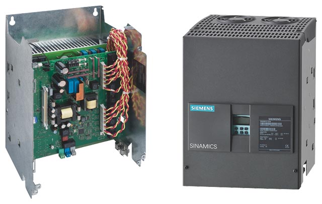
SINAMICS DC MASTER converters distinguish themselves as a result of the compact, space-saving design. The electronics module (available in various customer-specific combinations with options) is installed in a cradle that can be swiveled out. The easy access to individual components makes this technology very service-friendly.
Plug-in terminals are used to connect external signals (binary inputs/outputs, analog inputs/outputs, pulse generators etc.). The device software is saved in a flash EPROM and can be easily exchanged by loading via the serial interface of the SINAMICS DC MASTER.
Power section: Armature and field circuit
The armature circuit is implemented as a three-phase bridge circuit:
The field circuit is implemented in a half-controlled single-phase bridge circuit B2HZ.
In the case of units with a 15 A to 1 200 A rated DC current, the power sections for the armature and field include electrically isolated thyristor modules, which means that the heat sink is floating. For units up to 30 A, the armature and field power sections are implemented in the form of a printed circuit board with compact modules that are soldered on.
For units with rated currents ≥ 1 500 A, the power section for the armature circuit uses disc-type thyristors and heat sinks at voltage potential. For units from 1 500 to 3 000 A, the thyristor phases are implemented as plug-in modules and can therefore be quickly replaced.
Checking the motor insulation has been significantly simplified due to the fact that the line supply voltage sensing for the armature and the field sections is electrically isolated.
Cooling
Units with a rated DC current up to 125 A are designed for natural air cooling, units with a rated current above 210 A are designed for forced air cooling (fan). The fans are always horizontally mounted at the top so that they can be quickly replaced without having to disconnect the power connections.
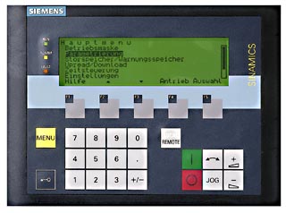
BOP20 Basic Operator Panel
BOP20 Basic Operator Panel
As standard, all of the units are equipped with a BOP20 Basic Operator Panel from the SINAMICS family.
The basic operator panel offers customers a basic functionality for commissioning as well as operator control and monitoring.
Faults can be acknowledged, parameters set and diagnostics information read-out (e.g. alarm and fault messages) using the BOP20.
The BOP20 has a backlit two-line display area and 6 keys.
The BOP20 power supply and communication with the CUD Control Unit are established via the connector integrated at the rear of the BOP20.
AOP30 Advanced Operator Panel
The AOP30 Advanced Operator Panel is an optional input/output device for SINAMICS DC MASTER converters. It can be separately ordered. Additional information on the AOP30 is available in section "Accessories and supplementary components".
PC based parameterization
The STARTER tool is available for PC-based commissioning and diagnostics. More detailed information is provided in section “Tools and Engineering”.
The closed-loop and open-loop drive control is essentially designed for supplying the armature and field of variable-speed DC drives.
Using BICO technology permits the closed-loop and open-loop drive control structure to be simply adapted to the application-specific requirements as well as the use in alternative applications (e.g. as excitation equipment for synchronous motors).
The most important functions of the closed-loop control include:
BICO technology
BICO technology (Binector Connector Technology) allows signal paths to be defined (and therefore the controller structure) using parameters.
Mode of operation:
All important points of the closed-loop control are accessible via connectors.
Connectors are measuring points that are mapped to display parameters.
Important connectors include:
All important binary signals of the closed-loop and open-loop control are accessible via binectors.
Binectors are measuring points for binary signals, which are mapped to display parameters.
Important binectors include:
All of the important inputs of the open-loop and closed-loop control can be interconnected using BICO selection parameters. This means that by setting the corresponding BICO selection parameter, a connection can be established between any connector or binector.
Important inputs include:
Data sets
Many open-loop and closed-loop control parameters depend on the particular data set. This means that they have several indices where various values can be set. All data set dependent parameters can be simultaneously switched over to another data set using binary control signals.
There are two groups of data set-dependent parameters:
By parameterizing several command data sets and switching between them, the drive can be operated with different pre-configured signal sources.
The SINAMICS DC MASTER converter units are supplied with the factory settings. Controller setting is supported by selecting automatic optimization runs. The selection is made using special key numbers.
The following controller functions can be set using an automatic optimization run:
Displaying operating values
The operating state of the converter is displayed using a parameter. Several hundred signals can be displayed via parameter or selected for output on the display unit. Examples of measured values that can be displayed: Setpoints, actual values, status of binary inputs/outputs, line supply voltage, line frequency, firing angle, inputs/outputs of the analog terminals, controller input and output, limits.
Trace function
Up to eight measured quantities can be saved by selecting the trace function. A measured quantity or the occurrence of a fault message can be parameterized as trigger condition. By selecting a trigger delay, it is also possible to record (trace) the pre-history and post-history of events. The sampling time of the measured value storage can be parameterized.
The measured values can be output via the serial interfaces using the STARTER commissioning tool.
Fault messages
A number is assigned to each fault message. In addition, the operating hour of the event is saved together with the fault message. This allows the cause of the fault to be quickly pinpointed. By using the optional AOP30 Advanced Operator Panel, fault messages can be stamped in real time. Then, instead of the operating hour of the event, the day and the time of day of the event are displayed in the AOP30 fault list. For diagnostic purposes, the last eight fault messages are saved with fault number, fault value and the operating hours.
When a fault occurs
Fault messages should either be acknowledged via the operator panel, a binary user-assignable terminal or a serial interface. The "switch-on inhibit" state is reached after the fault has been acknowledged. "Switch-on inhibit" is canceled by an OFF command.
Automatic restart: An automatic restart is possible within a time that can be parameterized between 0 and 10 s. If the time is set to zero, a fault message is immediately output (for power failure) without a restart. A restart can be selected for the following fault messages: Phase failure (field or armature), undervoltage, overvoltage, electronics power supply failure, undervoltage condition at the parallel SINAMICS DC MASTER.
A distinction is made between the following groups of fault messages:
The fault messages can be individually deactivated using a parameter. Some fault messages are already deactivated in the factory and can be activated using this parameter.
Alarms
Alarm messages display special states; however, they do not cause the drive to be switched-off. Alarms that occur do not have to be acknowledged, but rather they are automatically reset as soon as the cause of the alarm is no longer present.
When one or several alarms occur
A distinction is made between the following groups of alarms:
Analog user-assignable inputs
After converting to a digital value, the quantity of the analog inputs can be flexibly adapted via parameters for scaling, filter, sign selection and offset input. The values are available as connector. This is the reason that the analog inputs can be effective as main setpoint and also as quantity for a supplementary setpoint or a limit.
Analog outputs
Selectable analog outputs are available to output analog signals. Analog signals can be output as bipolar signal or as absolute value. In this case, scaling, an offset, polarity and a filter time can be parameterized. The required output quantities are selected at the intervention points by entering connector numbers. For instance, speed actual value, ramp-function generator output, current setpoint, line supply voltage etc. can be output.
Binary inputs
Binary user-assignable inputs:
Additional binary input terminals are available for user-assignable functions. In this case, a binector number is assigned to every user-assignable terminal, which can be used for control functions.
Examples of binary input functions:
Binary outputs
User-assignable signaling functions are available at the binary output terminals (open emitter output). Any binector quantity, which can be selected via the associated user-assignable parameter, can be output for each terminal. The polarity of the output signal and an adjustable delay time (0 to 10 s) can be selected using parameters.
Examples of binary output functions:
When switching on the drive using the "switch-on" function and entering "operating enable", an H signal is output to open the brake, in this case, the internal controller enable is delayed by a parameterizable time (wait for the mechanical brake opening time to expire). When shutting down the drive using the "shutdown" function or "fast stop", an L signal is output to close the brake when speed n < nmin is reached. At the same time, the internal controller enable is present for a parameterizable time (wait for the mechanical brake closing time to expire): When I = 0 is entered, the pulses are inhibited and the main contactor is opened.
An additional operating mode can be selected using the "close brake" signal (L signal at the binary user-assignable output). As a consequence, when the "internal controller inhibit" is present (the drive is in a no-current condition), the drive does not wait for the status n < nmin, but the brake is already controlled (operating brake) at speeds greater than nmin.
Internal control inhibit is present when a fault message occurs, when the voltage is disconnected or the operating enable - terminal operating enable - is withdrawn in operation.
The E-STOP function is used to open the relay contact for the main contactor control within approximately 15 ms independent of semiconductor components and the correct functioning of the CUD. If the CUD is operating correctly, entering I = 0 via the control ensures that the main contactor is switched in a no-current condition. The drive coasts down once E-STOP has been entered.
After the E-STOP has been reset, the drive goes into the "switch-on inhibit" operating state. This must be acknowledged by activating the "shutdown" function e.g. by opening terminal switch-on/shutdown.
Note:
The E-STOP function is not an EMERGENCY OFF function in the sense of EN 60204-1.
The following serial interfaces are available for each CUD:
Physics of the interfaces
USS protocol
Open Siemens protocol, can be simply programmed e.g. on the PC in third-party systems, any master interfaces can be used. The drives operate as slaves connected to a master. The drives are selected using a slave number.
The following data exchange is possible via the USS protocol:
The send data (actual values) are selected by entering connector numbers in the parameters, the receive data (setpoints) represent the connector numbers, that can act at any intervention points.
Peer-to-peer protocol
The peer-to-peer protocol is used to connect devices with one another. For this operating mode, data is exchanged between converters via a serial interface, e.g. to establish a setpoint cascade. By using a serial interface as four-conductor cable, data can be received from the previous unit that is then processed (e.g. by being multiplied) and then transferred to the following unit. Only one serial interface is used for this purpose.
The following data can be exchanged between converters:
In this case, up to five data words are transferred in both the send and receive directions. Data is exchanged via connector numbers and intervention points.
The serial interfaces can be simultaneously operated. A connection to the automation (USS protocol) can be established via the first interface for control, diagnostics and to enter the main setpoint. A second interface is used to realize a setpoint cascade function via the peer-to-peer protocol.
Terminals on the CUD
Terminals on the gating module
Motor temperature monitoring
Either PTC thermistors or linear temperature sensors (KTY84-130) can be connected. One input is provided on the Standard CUD and one input on the Advanced CUD option for this purpose. An alarm or fault message can be parameterized for PTC thermistors. When using a KTY84-130, one threshold can be entered for an alarm and one threshold for shutdown (trip). The limit values are displayed and entered in °C.
In addition, a thermo switch can be evaluated by the Advanced CUD (option). A parameterizable alarm or fault message can be output when the thermo switch responds (this is a binary switching signal). The evaluation is realized via a binary user-assignable input.
Brush length monitoring
The brush length is monitored using a floating microswitch; the shortest brush is evaluated. If the useful brush life has expired, then the microswitch opens; an alarm or fault message can be parameterized. The evaluation is realized via a binary user-assignable input.
Monitoring the motor fan airflow
An airflow monitor is integrated in the airflow of the motor fan. When this responds, an alarm or fault message is issued. The evaluation is realized via a binary user-assignable input.
Although the end of DC technology has been forecast now for many years, we will keep hold of our DC technology and it will remain in our portfolio. When all is said and done, DC motors have proven themselves in daily use for decades now and they are essentially indispensable.
In conjunction with the SINAMICS DC MASTER converters, they always form the ideal team – wherever favorably-priced drive technology and the highest degree of availability are demanded.
These motors can also be used where space is restricted thanks to their compact and modular design.
Further, an extensive range of equipment and devices for mounting on the motor is available. A wide range of monitoring and diagnostic options facilitate reliable and disturbance-free operation.
Detailed specifications regarding quality assurance and improvement are integrated in all of the various operations and processes - from motor development through to production and service. Quality management coordinates the interaction between all of the company processes to ensure error-free and smooth processes.
It goes without saying that our stringent quality requirements also apply to our suppliers. All of the suppliers must seamlessly integrate themselves into our quality management system.
The result: Only fault-free and high quality materials are released for use in our motor production.
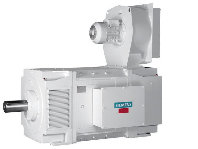
Customer benefits:
Technical data | |
|---|---|
Power range | 31.5 … 1 610 kW |
Rated armature voltage | 420 … 810 V DC |
Field | Separately excited |
Shaft heights | 160 … 630 mm |
Number of poles | 4- and 6-pole |
Speed | Up to 4 500 rpm |
Degree of protection | IP23 and IP54 |
Type of construction | IM B3, IM B35, IM V1 and others |
Cooling method | IC06/IC17/IC37/IC A06 A66/IC W37 A86 |
Stator version | Fully laminated |
Standards | IEC, EN, DIN, VDE |
Operation | Converter operation, 2Q and 4Q, S1 – S9 |
Typical applications:
Additional information on Siemens DC motors is available in the Internet under:
http://www.automation.siemens.com/ld/dc-motor
| Код | Заказной номер | Описание | Вес (кг) | Заказать |
|---|---|---|---|---|
| 114823 | 6RA8013-6DV62-0AA0 | sinamics dcm dc converter for four-quadrant drives connection (b6) a (b6) c input: 3-phase ac 400v, 13a controllable field rectifier d420/15 mreq-geg6v62 output: dc 420v, 15a | 6 | Заказать |
| 114824 | 6RA8013-6FV62-0AA0 | sinamics dcm dc converter for four-quadrant drives connection (b6) a (b6) c input: 3-phase ac 480v, 12a controllable field rectifier d500/15 mreq-geg6v62 output: dc 500v, 15a | 6 | Заказать |
| 66749 | 6RA8018-6DV62-0AA0 | sinamics dcm dc converter for four-quadrant drives connection (b6) a (b6) c input: 3-phase ac 400v, 25a controllable field rectifier d420/30 mreq-geg6v62 output: dc 420v, 30a | 6 | Заказать |
| 114825 | 6RA8018-6FV62-0AA0 | sinamics dcm dc converter for four-quadrant drives connection (b6) a (b6) c input: 3-phase ac 480v, 25a controllable field rectifier d500/30 mreq-geg6v62 output: dc 500v, 30a | 6 | Заказать |
| 66750 | 6RA8025-6DS22-0AA0 | sinamics dcm dc converter for two-quadrant drives connection b6c input: 3-phase ac 400v, 50a controllable field rectifier d485/60 mre-gee6s22 output: dc 485v, 60a | 12 | Заказать |
| 66751 | 6RA8025-6DV62-0AA0 | sinamics dcm dc converter for four-quadrant drives connection (b6) a (b6) c input: 3-phase ac 400v, 50a controllable field rectifier d420/60 mreq-geg6v62 output: dc 420v, 60a | 12 | Заказать |
| 66752 | 6RA8025-6FS22-0AA0 | sinamics dcm dc converter for two-quadrant drives connection b6c input: 3-phase ac 480v, 50a controllable field rectifier d575/60 mre-gee6s22 output: dc 575v, 60a | 12 | Заказать |
| 66753 | 6RA8025-6FV62-0AA0 | sinamics dcm dc converter for four-quadrant drives connection (b6) a (b6) c input: 3-phase ac 480v, 50a controllable field rectifier d500/60 mreq-geg6v62 output: dc 500v, 60a | 12 | Заказать |
| 66754 | 6RA8025-6GS22-0AA0 | sinamics dcm dc converter for two-quadrant drives connection b6c input: 3-phase ac 575v, 50a controllable field rectifier d690/60 mre-gee6s22 output: dc 690v, 60a | 12 | Заказать |
| 114826 | 6RA8025-6GV62-0AA0 | sinamics dcm dc converter for four-quadrant drives connection (b6) a (b6) c input: 3-phase ac 575v, 50a controllable field rectifier d600/60 mreq-geg6v62 output: dc 600v, 60a | 12 | Заказать |
| 66755 | 6RA8028-6DS22-0AA0 | sinamics dcm dc converter for two-quadrant drives connection b6c input: 3-phase ac 400v, 75a controllable field rectifier d485/90 mre-gee6s22 output: dc 485v, 90a | 15 | Заказать |
| 114827 | 6RA8028-6DV62-0AA0 | sinamics dcm dc converter for four-quadrant drives connection (b6) a (b6) c input: 3-phase ac 400v, 75a controllable field rectifier d420/90 mreq-geg6v62 output: dc 420v, 90a | 15 | Заказать |
| 114828 | 6RA8028-6FS22-0AA0 | sinamics dcm dc converter for two-quadrant drives connection b6c input: 3-phase ac 480v, 75a controllable field rectifier d575/90 mre-gee6s22 output: dc 575v, 90a | 15 | Заказать |
| 66756 | 6RA8028-6FV62-0AA0 | sinamics dcm dc converter for four-quadrant drives connection (b6) a (b6) c input: 3-phase ac 480v, 75a controllable field rectifier d500/90 mreq-geg6v62 output: dc 500v, 90a | 15 | Заказать |
| 66757 | 6RA8031-6DS22-0AA0 | sinamics dcm dc converter for two-quadrant drives connection b6c input: 3-phase ac 400v, 104a controllable field rectifier d485/125 mre-gee6s22 output: dc 485v, 125a | 15 | Заказать |
| 114829 | 6RA8031-6DV62-0AA0 | sinamics dcm dc converter for four-quadrant drives connection (b6) a (b6) c input: 3-phase ac 400v, 104a controllable field rectifier d420/125 mreq-geg6v62 output: dc 420v, 125a | 15 | Заказать |
| 114830 | 6RA8031-6FS22-0AA0 | sinamics dcm dc converter for two-quadrant drives connection b6c input: 3-phase ac 480v, 104a controllable field rectifier d575/125 mre-gee6s22 output: dc 575v, 125a | 15 | Заказать |
| 114831 | 6RA8031-6FV62-0AA0 | sinamics dcm dc converter for four-quadrant drives connection (b6) a (b6) c input: 3-phase ac 480v, 104a controllable field rectifier d500/125 mreq-geg6v62 output: dc 500v, 125a | 15 | Заказать |
| 66758 | 6RA8031-6GS22-0AA0 | sinamics dcm dc converter for two-quadrant drives connection b6c input: 3-phase ac 575v, 104a controllable field rectifier d690/125 mre-gee6s22 output: dc 690v, 125a | 15 | Заказать |
| 114832 | 6RA8031-6GV62-0AA0 | sinamics dcm dc converter for four-quadrant drives connection (b6) a (b6) c input: 3-phase ac 575v, 104a controllable field rectifier d600/125 mreq-geg6v62 output: dc 600v, 125a | 15 | Заказать |
| 66759 | 6RA8075-6DS22-0AA0 | sinamics dcm dc converter for two-quadrant drives connection b6c input: 3-phase ac 400v, 174a controllable field rectifier d485/210 mre-geef6s22 output: dc 485v, 210a | 15 | Заказать |
| 114833 | 6RA8075-6DV62-0AA0 | sinamics dcm dc converter for four-quadrant drives connection (b6) a (b6) c input: 3-phase ac 400v, 174a controllable field rectifier d420/210 mreq-gegf6v62 output: dc 420v, 210a | 15 | Заказать |
| 114834 | 6RA8075-6FS22-0AA0 | sinamics dcm dc converter for two-quadrant drives connection b6c input: 3-phase ac 480v, 174a controllable field rectifier d575/210 mre-geef6s22 output: dc 575v, 210a | 15 | Заказать |
| 114835 | 6RA8075-6FV62-0AA0 | sinamics dcm dc converter for four-quadrant drives connection (b6) a (b6) c input: 3-phase ac 480v, 174a controllable field rectifier d500/210 mreq-gegf6v62 output: dc 500v, 210a | 15 | Заказать |
| 66760 | 6RA8075-6GS22-0AA0 | sinamics dcm dc converter for two-quadrant drives connection b6c input: 3-phase ac 575v, 174a controllable field rectifier d690/210 mre-geef6s22 output: dc 690v, 210a | 15 | Заказать |
| 114836 | 6RA8075-6GV62-0AA0 | sinamics dcm dc converter for four-quadrant drives connection (b6) a (b6) c input: 3-phase ac 575v, 174a controllable field rectifier d600/210 mreq-gegf6v62 output: dc 600v, 210a | 15 | Заказать |
| 114837 | 6RA8078-6DS22-0AA0 | sinamics dcm dc converter for two-quadrant drives connection b6c input: 3-phase ac 400v, 232a controllable field rectifier d485/280 mre-geef6s22 output: dc 485v, 280a | 15 | Заказать |
| 114838 | 6RA8078-6DV62-0AA0 | sinamics dcm dc converter for four-quadrant drives connection (b6) a (b6) c input: 3-phase ac 400v, 232a controllable field rectifier d420/280 mreq-gegf6v62 output: dc 420v, 280a | 15 | Заказать |
| 114839 | 6RA8078-6FS22-0AA0 | sinamics dcm dc converter for two-quadrant drives connection b6c input: 3-phase ac 480v, 232a controllable field rectifier d575/280 mre-geef6s22 output: dc 575v, 280a | 15 | Заказать |
| 66761 | 6RA8078-6FV62-0AA0 | sinamics dcm dc converter for four-quadrant drives connection (b6) a (b6) c input: 3-phase ac 480v, 232a controllable field rectifier d500/280 mreq-gegf6v62 output: dc 500v, 280a | 15 | Заказать |
| 66762 | 6RA8081-6DS22-0AA0 | sinamics dcm dc converter for two-quadrant drives connection b6c input: 3-phase ac 400v, 332a controllable field rectifier d485/400 mre-geef6s22 output: dc 485v, 400a | 28 | Заказать |
| 114840 | 6RA8081-6DV62-0AA0 | sinamics dcm dc converter for four-quadrant drives connection (b6) a (b6) c input: 3-phase ac 400v, 332a controllable field rectifier d420/400 mreq-gegf6v62 output: dc 420v, 400a | 28 | Заказать |
| 66763 | 6RA8081-6GS22-0AA0 | sinamics dcm dc converter for two-quadrant drives connection b6c input: 3-phase ac 575v, 332a controllable field rectifier d690/400 mre-geef6s22 output: dc 690v, 400a | 28 | Заказать |
| 114841 | 6RA8081-6GV62-0AA0 | sinamics dcm dc converter for four-quadrant drives connection (b6) a (b6) c input: 3-phase ac 575v, 332a controllable field rectifier d600/400 mreq-gegf6v62 output: dc 600v, 400a | 28 | Заказать |
| 114842 | 6RA8082-6FS22-0AA0 | sinamics dcm dc converter for two-quadrant drives connection b6c input: 3-phase ac 480v, 374a controllable field rectifier d575/450 mre-geef6s22 output: dc 575v, 450a | 28 | Заказать |
| 114843 | 6RA8082-6FV62-0AA0 | sinamics dcm dc converter for four-quadrant drives connection (b6) a (b6) c input: 3-phase ac 480v, 374a controllable field rectifier d500/450 mreq-gegf6v62 output: dc 500v, 450a | 28 | Заказать |
| 66764 | 6RA8085-6DS22-0AA0 | sinamics dcm dc converter for two-quadrant drives connection b6c input: 3-phase ac 400v, 498a controllable field rectifier d485/600 mre-geef6s22 output: dc 485v, 600a | 31 | Заказать |
| 66765 | 6RA8085-6DV62-0AA0 | sinamics dcm dc converter for four-quadrant drives connection (b6) a (b6) c input: 3-phase ac 400v, 498a controllable field rectifier d420/600 mreq-gegf6v62 output: dc 420v, 600a | 31 | Заказать |
| 114844 | 6RA8085-6FS22-0AA0 | sinamics dcm dc converter for two-quadrant drives connection b6c input: 3-phase ac 480v, 498a controllable field rectifier d575/600 mre-geef6s22 output: dc 575v, 600a | 31 | Заказать |
| 66766 | 6RA8085-6FV62-0AA0 | sinamics dcm dc converter for four-quadrant drives connection (b6) a (b6) c input: 3-phase ac 480v, 498a controllable field rectifier d500/600 mreq-gegf6v62 output: dc 500v, 600a | 31 | Заказать |
| 114845 | 6RA8085-6GS22-0AA0 | sinamics dcm dc converter for two-quadrant drives connection b6c input: 3-phase ac 575v. 498a controllable field rectifier d690/600 mre-geef6s22 output: dc 690v, 600a | 31 | Заказать |
| 114846 | 6RA8085-6GV62-0AA0 | sinamics dcm dc converter for four-quadrant drives connection (b6) a (b6) c input: 3-phase ac 575v, 498a controllable field rectifier d600/600 mreq-gegf6v62 output: dc 600v, 600a | 31 | Заказать |
| 66767 | 6RA8086-6KS22-0AA0 | sinamics dcm dc converter for two-quadrant drives connection b6c input: 3-phase ac 690v, 598a controllable field rectifier d830/720 mre-geef6s22 output: dc 830v, 720a | 42 | Заказать |
| 114847 | 6RA8086-6KV62-0AA0 | sinamics dcm dc converter for four-quadrant drives connection (b6) a (b6) c input: 3-phase ac 690v, 631a controllable field rectifier d725/760 mreq-gegf6v62 output: dc 725v, 760a | 42 | Заказать |
| 114848 | 6RA8087-6DS22-0AA0 | sinamics dcm dc converter for two-quadrant drives connection b6c input: 3-phase ac 400v, 706a controllable field rectifier d485/850 mre-geef6s22 output: dc 485v, 850a | 42 | Заказать |
| 114849 | 6RA8087-6DV62-0AA0 | sinamics dcm dc converter for four-quadrant drives connection (b6) a (b6) c input: 3-phase ac 400v, 706a controllable field rectifier d420/850 mreq-gegf6v62 output: dc 420v, 850a | 42 | Заказать |
| 114850 | 6RA8087-6FS22-0AA0 | sinamics dcm dc converter for two-quadrant drives connection b6c input: 3-phase ac 480v, 706a controllable field rectifier d575/850 mre-geef6s22 output: dc 575v, 850a | 42 | Заказать |
| 66768 | 6RA8087-6FV62-0AA0 | sinamics dcm dc converter for four-quadrant drives connection (b6) a (b6) c input: 3-phase ac 480v, 706a controllable field rectifier d500/850 mreq-gegf6v62 output: dc 500v, 850a | 42 | Заказать |
| 114851 | 6RA8087-6GS22-0AA0 | sinamics dcm dc converter for two-quadrant drives connection b6c input: 3-phase ac 575v, 664a controllable field rectifier d690/800 mre-geef6s22 output: dc 690v, 800a | 42 | Заказать |
| 66769 | 6RA8087-6GV62-0AA0 | sinamics dcm dc converter for four-quadrant drives connection (b6) a (b6) c input: 3-phase ac 575v, 706a controllable field rectifier d600/850 mreq-gegf6v62 output: dc 600v, 850a | 42 | Заказать |
| 114852 | 6RA8088-6LS22-0AA0 | sinamics dcm dc converter for two-quadrant drives connection b6c input: 3-phase ac 830v, 789a controllable field rectifier d1000/950 mre-geef6s22 output: dc 1000v, 950a | 78 | Заказать |
| 114853 | 6RA8088-6LV62-0AA0 | sinamics dcm dc converter for four-quadrant drives connection (b6) a (b6) c input: 3-phase ac 830v, 789a controllable field rectifier d875/950 mreq-gegf6v62 output: dc 875v, 950a | 78 | Заказать |
| 114854 | 6RA8090-6GS22-0AA0 | sinamics dcm dc converter for two-quadrant drives connection b6c input: 3-phase ac 575v, 913a controllable field rectifier d690/1100 mre-geef6s22 output: dc 690v, 1100a | 78 | Заказать |
| 66770 | 6RA8090-6GV62-0AA0 | sinamics dcm dc converter for four-quadrant drives connection (b6) a (b6) c input: 3-phase ac 575v, 913a controllable field rectifier d600/1100 mreq-gegf6v62 output: dc 600v, 1100a | 78 | Заказать |
| 66771 | 6RA8090-6KS22-0AA0 | sinamics dcm dc converter for two-quadrant drives connection b6c input: 3-phase ac 690v, 830a controllable field rectifier d830/1000 mre-geef6s22 output: dc 830v, 1000a | 78 | Заказать |
| 66772 | 6RA8090-6KV62-0AA0 | sinamics dcm dc converter for four-quadrant drives connection (b6) a (b6) c input: 3-phase ac 690v, 830a controllable field rectifier d725/1000 mreq-gegf6v62 output: dc 725v, 1000a | 78 | Заказать |
| 66773 | 6RA8091-6DS22-0AA0 | sinamics dcm dc converter for two-quadrant drives connection b6c input: 3-phase ac 400v, 996a controllable field rectifier d485/1200 mre-geef6s22 output: dc 485v, 1200a | 78 | Заказать |
| 66774 | 6RA8091-6DV62-0AA0 | sinamics dcm dc converter for four-quadrant drives connection (b6) a (b6) c input: 3-phase ac 400v, 996a controllable field rectifier d420/1200 mreq-gegf6v62 output: dc 420v, 1200a | 78 | Заказать |
| 114855 | 6RA8091-6FS22-0AA0 | sinamics dcm dc converter for two-quadrant drives connection b6c input: 3-phase ac 480v, 996a controllable field rectifier d575/1200 mre-geef6s22 output: dc 575v, 1200a | 78 | Заказать |
| 66775 | 6RA8091-6FV62-0AA0 | sinamics dcm dc converter for four-quadrant drives connection (b6) a (b6) c input: 3-phase ac 480v, 996a controllable field rectifier d500/1200 mreq-gegf6v62 output: dc 500v, 1200a | 78 | Заказать |
| 66776 | 6RA8093-4DS22-0AA0 | sinamics dcm dc converter for two-quadrant drives connection b6c input: 3-phase ac 400v, 1328a controllable field rectifier d485/1600 mre-geef4s22 output: dc 485v, 1600a | 132 | Заказать |
| 66777 | 6RA8093-4DV62-0AA0 | sinamics dcm dc converter for four-quadrant drives connection (b6) a (b6) c input: 3-phase ac 400v, 1328a controllable field rectifier d420/1600 mreq-gegf4v62 output: dc 420v, 1600a | 151 | Заказать |
| 114856 | 6RA8093-4GS22-0AA0 | sinamics dcm dc converter for two-quadrant drives connection b6c input: 3-phase ac 575v, 1328a controllable field rectifier d690/1600 mre-geef4s22 output: dc 690v, 1600a | 132 | Заказать |
| 114857 | 6RA8093-4GV62-0AA0 | sinamics dcm dc converter for four-quadrant drives connection (b6) a (b6) c input: 3-phase ac 575v, 1328a controllable field rectifier d600/1600 mreq-gegf4v62 output: dc 600v, 1600a | 151 | Заказать |
| 114858 | 6RA8093-4KS22-0AA0 | sinamics dcm dc converter for two-quadrant drives connection b6c input: 3-phase ac 690v, 1245a controllable field rectifier d830/1500 mre-geef4s22 output: dc 830v, 1500a | 132 | Заказать |
| 66778 | 6RA8093-4KV62-0AA0 | sinamics dcm dc converter for four-quadrant drives connection (b6) a (b6) c input: 3-phase ac 690v, 1245a controllable field rectifier d725/1500 mreq-gegf4v62 output: dc 725v, 1500a | 151 | Заказать |
| 66779 | 6RA8093-4LS22-0AA0 | sinamics dcm dc converter for two-quadrant drives connection b6c input: 3-phase ac 830v, 1245a controllable field rectifier d1000/1500 mre-geef4s22 output: dc 1000v,1500a | 132 | Заказать |
| 114859 | 6RA8093-4LV62-0AA0 | sinamics dcm dc converter for four-quadrant drives connection (b6) a (b6) c input: 3-phase ac 830v, 1245a controllable field rectifier d875/1500 mreq-gegf4v62 output: dc 875v, 1500a | 151 | Заказать |
| 114860 | 6RA8095-4DS22-0AA0 | sinamics dcm dc converter for two-quadrant drives connection b6c input: 3-phase ac 400v, 1660a controllable field rectifier d485/2000 mre-geef4s22 output: dc 485v, 2000a | 132 | Заказать |
| 66780 | 6RA8095-4DV62-0AA0 | sinamics dcm dc converter for four-quadrant drives connection (b6) a (b6) c input: 3-phase ac 400v, 1660a controllable field rectifier d420/2000 mreq-gegf4v62 output: dc 420v, 2000a | 151 | Заказать |
| 66781 | 6RA8095-4GS22-0AA0 | sinamics dcm dc converter for two-quadrant drives connection b6c input: 3-phase ac 575v, 1660a controllable field rectifier d690/2000 mre-geef4s22 output: dc 690v, 2000a | 132 | Заказать |
| 66782 | 6RA8095-4GV62-0AA0 | sinamics dcm dc converter for four-quadrant drives connection (b6) a (b6) c input: 3-phase ac 575v, 1660a controllable field rectifier d600/2000 mreq-gegf4v62 output: dc 600v, 2000a | 151 | Заказать |
| 66783 | 6RA8095-4KS22-0AA0 | sinamics dcm dc converter for two-quadrant drives connection b6c input: 3-phase ac 690v, 1660a controllable field rectifier d830/2000 mre-geef4s22 output: dc 830v, 2000a | 132 | Заказать |
| 114861 | 6RA8095-4KV62-0AA0 | sinamics dcm dc converter for four-quadrant drives connection (b6) a (b6) c input: 3-phase ac 690v, 1660a controllable field rectifier d725/2000 mreq-gegf4v62 output: dc 725v, 2000a | 151 | Заказать |
| 114862 | 6RA8095-4LS22-0AA0 | sinamics dcm dc converter for two-quadrant drives connection b6c input: 3-phase ac 830v, 1577a controllable field rectifier d1000/1900 mre-geef4s22 output: dc 1000v,1900a | 132 | Заказать |
| 114863 | 6RA8095-4LV62-0AA0 | sinamics dcm dc converter for four-quadrant drives connection (b6) a (b6) c input: 3-phase ac 830v, 1577a controllable field rectifier d875/1900 mreq-gegf4v62 output: dc 875v, 1900a | 151 | Заказать |
| 66784 | 6RA8096-4GS22-0AA0 | sinamics dcm dc converter for two-quadrant drives connection b6c input: 3-phase ac 575v, 1826a controllable field rectifier d690/2200 mre-geef4s22 output: dc 690v, 2200a | 132 | Заказать |
| 66785 | 6RA8096-4GV62-0AA0 | sinamics dcm dc converter for four-quadrant drives connection (b6) a (b6) c input: 3-phase ac 575v, 1826a controllable field rectifier d600/2200 mreq-gegf4v62 output: dc 600v, 2200a | 151 | Заказать |
| 66786 | 6RA8096-4MS22-0AA0 | sinamics dcm dc converter for two-quadrant drives connection b6c input: 3-phase ac 950v, 1826a controllable field rectifier d1140/2200 mre-geef4s22 output: dc 1140v, 2200a | 163 | Заказать |
| 66787 | 6RA8096-4MV62-0AA0 | sinamics dcm dc converter for four-quadrant drives connection (b6) a (b6) c input: 3-phase ac 950v, 1826a controllable field rectifier d1000/2200 mreq-gegf4v62 output: dc 1000v, 2200a | 182 | Заказать |
| 114864 | 6RA8097-4GS22-0AA0 | sinamics dcm dc converter for two-quadrant drives connection b6c input: 3-phase ac 575v, 2324a controllable field rectifier d690/2800 mre-geef4s22 output: dc 690v, 2800a | 163 | Заказать |
| 114865 | 6RA8097-4GV62-0AA0 | sinamics dcm dc converter for four-quadrant drives connection (b6) a (b6) c input: 3-phase ac 575v, 2324a controllable field rectifier d600/2800 mreq-gegf4v62 output: dc 600v, 2800a | 182 | Заказать |
| 66788 | 6RA8097-4KS22-0AA0 | sinamics dcm dc converter for two-quadrant drives connection b6c input: 3-phase ac 690v, 2158a controllable field rectifier d830/2600 mre-geef4s22 output: dc 830v, 2600a | 163 | Заказать |
| 114866 | 6RA8097-4KV62-0AA0 | sinamics dcm dc converter for four-quadrant drives connection (b6) a (b6) c input: 3-phase ac 690v, 2158a controllable field rectifier d725/2600 mreq-gegf4v62 output: dc 725v, 2600a | 182 | Заказать |
| 66789 | 6RA8098-4DS22-0AA0 | sinamics dcm dc converter for two-quadrant drives connection b6c input: 3-phase ac 400v, 2490a controllable field rectifier d485/3000 mre-geef4s22 output: dc 485v, 3000a | 163 | Заказать |
| 66790 | 6RA8098-4DV62-0AA0 | sinamics dcm dc converter for four-quadrant drives connection (b6) a (b6) c input: 3-phase ac 400v, 2490a controllable field rectifier d420/3000 mreq-gegf4v62 output: dc 420v, 3000a | 182 | Заказать |
